- AI Development Use ML tools and algorithms to build intelligent AI-driven apps
- Generative AI Build intelligent generative AI solutions that adapt and evolve
- ML Development Build and deploy custom ML models to automate tasks
- MLOps Build sophisticated ML and CI/CD pipelines and shorten production cycles
- LLM Development Accelerate LLM adoption and streamline its implementation
- Data Science Consulting Get expert guidance to leverage data for operational improvements
- Gen AI and ML Build domain-specific generative AI solutions on AWS
- Migration and Modernization Move your current workloads to AWS Cloud environment
- SaaS Migration and Engineering Build, migrate, and optimize SaaS applications through cloud-native solution
- Data Science and Engineering Build and optimize your data processing pipelines to improve operational efficiency
- Serverless Manage complex workflows and ensure optimal resource utilization
- Cloud Management Improve AWS efficiency, automation, and visibility for better cloud operations
- Product Engineering and Development Build products powered by latest tech stacks and design thinking
- Custom Software Development Build scalable, robust software designed to meet your business needs
- Performance Engineering and Testing Build products that perform optimally in normal and extreme load conditions
- Quality Engineering Ensure product quality and customer satisfaction
- Project Strategy Build an agile, adaptive, and transformative project strategy
- Digital Experience Design Create digital experiences that engage users at every touch point
- Financial Services Build secure, scalable, precision-engineered BFSI solutions
- Retail and E-commerce Ensure a consistent customer experience and operational efficiency
- Healthcare and Life Sciences Build secure, compliant solutions for better patient care and improved efficiency
- Supply Chain & Logistics Bring agility, resilience, and intelligence to your supply chain
- Marketing and Technology Transform marketing efforts and optimize campaigns through intelligent automation
- Manufacturing Adopt modern solutions to automate workflow and improve product quality
- Case Studies
- AI & ML Insights Gain insights on the latest stories, reports, surveys, and updates on AI/ML
- Product Engineering Insights Get a deeper understanding of product development with our expert insights
- Cloud Engineering Insights Stay updated with the latest trends and best practices in cloud engineering
- Blog A collection of insights on latest technology, best practices and proven strategies
- Ebooks Download ebooks from our experts to know the winning strategies, technologies, and trends
- News and Tech Insights Keep up with the latest technology news and insights

Mobile Application Architecture: Layers, Types, Principles, Factors
A comprehensive guide on mobile application architecture covering layers, principles, factors, types, patterns, and examples.

Table of Contents
What is mobile application architecture.
- Key principles
- Choosing right mobile application architecture
Mobile apps open the gateway to our digital world. With nearly 7 billion smartphone users today and growing to over 7.7 billion by 2028 , mobile is the undisputed platform of the future. Mobile commands 59% of internet traffic worldwide as of Q4 2023. And get this – we downloaded a staggering 257 billion apps in 2023 !
These eye-popping stats clarify one thing: mobile apps are how we engage with products and services. As a business, an innovative mobile app is no longer optional – it’s imperative. But what transforms a good app into a game-changing one? The answer lies in its architecture.
In this post, we’ll walk you through mobile app architecture – its definition, layers, principles, factors, types, examples, and the knowledge to architect enterprise mobile apps.
Transform your app ideas into reality with Simform’s mobile app development services ! Our team crafts mobile app architectures tailored to your needs, ensuring scalability and performance. Connect with our experts to create a high ROI-delivering mobile app.
Mobile app architecture is the blueprint for building your app. The rules, processes, and structure determine how components like the front-end UI, backend database, APIs, etc, interact to process inputs and give outputs.
Think of architecture as the internal skeleton that supports your app’s outward function and form. Like a human skeleton enables walking, the architecture allows your app to “walk and talk” – taking in user inputs and serving the right content.
The architecture is the framework, while the tech stack is the technologies used to implement each component.
Importance of a good mobile app architecture
A well-designed mobile app architecture is crucial to create robust, scalable, and user-friendly applications. It offers several benefits that contribute to app’s success:
Firstly, it enhances modularity, allowing different app components to be developed and maintained independently, leading to easier updates and modifications. For instance, in an e-commerce app, a modular architecture enables seamless integration of new payment gateways without affecting other functionalities.
Secondly, robust security measures in the architecture ensure data protection and prevent unauthorized access. A banking app, for instance, can be fortified with encryption protocols and secure authentication methods, instilling trust among users and safeguarding their sensitive information
Moreover, reliability is heightened as a well-structured architecture minimizes bugs and errors, providing users a seamless experience. Think about a messaging app that rarely crashes or experiences glitches due to its meticulously designed architecture.
Furthermore, performance and scalability are optimized, allowing the app to handle increasing user loads and adapt to growing demands over time. An example is a social media platform capable of accommodating millions of users concurrently without compromising speed or functionality.
Lastly, an excellent mobile app architecture has different layers that structure the application into logical components with distinct roles for robust and scalable mobile apps .
Layers of mobile application architecture
Most mobile app architectures have three layers: presentation, business, and data.

1. Presentation layer
The presentation layer, or front end, is the user interface (UI) you see when opening an app. It includes the screens, navigation, controls, and visual elements. For example, in a messaging app like WhatsApp , the presentation layer comprises chat screens, contact lists, settings menus, etc. Its primary function is to enable user interactions by taking input from users and displaying output from the lower layers.
2. Business layer
The business layer contains the core application logic that handles tasks like computations, validations, analytics, notifications, background jobs, etc.
In a messaging app, this layer handles functions like sending and receiving messages, encrypting data, detecting spam, managing notifications, etc. It takes input from the presentation and data layers, processes it, and prepares the responses displayed in the UI.
3. Data layer
The data layer handles connections to databases and storage systems, allowing the app to save and retrieve data. For example, in WhatsApp, message data is stored in various databases.
The data layer abstracts the physical storage, so other layers don’t need to worry about the specifics of databases. It handles queries, connections, caching, concurrency, and other data access mechanics. The business layer interacts with the data layer by calling methods it exposes.
Types of mobile application architecture
There are three major types of mobile application architecture – layered, monolithic, and microservice. Let’s explore each of them in detail.
1. Layered architecture

Layered architecture organizes the application into layers, each responsible for a specific aspect of the application’s functionality. Typically, these layers include presentation, business logic, and data access layers.
This architecture promotes modularity and separation of concerns, which makes it easier to maintain and scale the application. However, if not implemented carefully, it may lead to tight coupling between layers.
Layered architecture works well for large, complex applications that require frequent updates. By isolating frontend, business, and data layers, you can focus on specific components and accelerate development and testing cycles for iterative delivery.
2. Monolithic architecture

Monolithic architecture structures the entire application as a single, tightly integrated unit. All application components, including the user interface, business logic, and data access, are packaged together and deployed as a single entity.
While this architecture can simplify development and deployment, it can also lead to scalability and maintainability issues as the application grows in size and complexity.
Monolithic architecture gives you a lightweight, all-in-one bundle for simple apps with well-defined, stable requirements. Since everything is tightly coupled, development and deployment can be fast, especially for apps with limited scope and low chances of change.
3. Microservice architecture
The microservice architecture breaks the application into smaller, independent services, each responsible for specific functionalities. These services communicate through APIs, offering flexibility and scalability.
You can develop, deploy, and scale microservices independently, making updating and maintaining the application easier. However, managing many services can introduce complexity, and additional overhead may be associated with coordinating communication between services.
Microservices architecture excels when you need to update complex apps and scale them across multiple teams frequently. By decomposing into discrete services, you can independently develop, deploy, and scale components to accelerate iteration for large, evolving applications.
Key principles of mobile application architecture
Like pillars supporting a building, principles in mobile architecture provide foundational guidance so you can construct an app that is stable, scalable, and prepared for future growth.

Let’s explore vital architectural principles you should consider when designing mobile apps:
| Flexibility | The architecture can adapt to changing requirements and new technologies |
| Maintainability | The app is easy to maintain via modularity, loose coupling, and encapsulation |
| Reusability | Components and modules can be reused across applications |
| Security | Data and identity are protected through access controls and encryption |
| Performance | The app delivers speed, reliability, and resource efficiency |
| Sustainability | The architecture supports continuity over changes and future growth |
| Extensibility | New capabilities can be added via plugins, extensions, and integrations |
| Testability | Components can be easily tested in isolation |
| Intuitiveness | The architecture follows established and familiar patterns |
| Portability | The app can be deployed on different mobile platforms |
Factors to consider while designing a mobile app architecture
Device type, user interface, push notifications, navigation method, etc., are a few of the several factors that help build a robust mobile app architecture.
Let’s discuss them briefly:

a. Device type
The device type determines the hardware capabilities and screen sizes your utility needs to support. For example, designing an app for smartphones and tablets requires accommodating different screen resolutions and aspect ratios.
Imagine you’re developing a fitness-tracking application. In that case, you should ensure that these small smartphone screens are optimized for large tablet displays for an immersive user experience regardless of the device used.
When evaluating device types for your mobile app architecture, you must consider features like screen size, resolution, memory, processors, battery life, sensors, camera capabilities, and OS versions.
b. Development framework
Selecting the right development framework is vital for efficient application development and maintenance. For example, if you aim to build cross-platform applications, frameworks like React Native or Flutter allow you to write code once and deploy it across multiple platforms.
On the other hand, if you prioritize performance and native experience, platform-specific frameworks like Swift for iOS or Kotlin for Android might be preferable.
If you’re unsure about choosing the right platform or need assistance with mobile app development, consider partnering with Simform. As a leading mobile app development company , Simform offers a team of experienced and seasoned mobile app developers who can help you create mobile apps that meets your business requirements.
c. Bandwidth
The available bandwidth directly impacts how your app communicates with servers and fetches data. Designing your app to minimize data usage becomes paramount in regions with limited internet connectivity. For instance, if creating a video streaming app , you might implement adaptive bit streaming to adjust video quality based on the user’s network speed, ensuring smooth playback even in low bandwidth conditions.
d. Network fluctuations
Mobile networks are prone to varying signal strength and stability fluctuations, which can affect app performance. Designing your app to handle network fluctuations gracefully is essential for providing a seamless user experience. Implementing caching mechanisms to store frequently accessed data locally can reduce reliance on real-time network requests and mitigate the impact of temporary network outages.
e. User interface
The user interface (UI) plays a crucial role in shaping the overall user experience of your app. It should be intuitive, visually appealing, and consistent across different devices and screen sizes. For instance, if you are designing a shopping app, you should prioritize easy navigation, intuitive search functionality, and visually appealing product displays to enhance the shopping experience for users.
f. Navigation method
The navigation method defines how users navigate your app and access its features and content. Whether you opt for tab-based navigation, drawer menus, or bottom navigation bars depends on the complexity of your app and user preferences. For example, a news app might use tab-based navigation to allow users to quickly switch between different sections like top stories, sports, and entertainment.
g. Real-time updates vs. push notifications
Deciding between real-time updates and push notifications depends on the nature of your app and the importance of timely information delivery. For example, a messaging app requires real-time updates to ensure instant user communication. In contrast, a news app might use push notifications to notify users of breaking news stories or personalized updates based on their interests.
Mobile app architecture patterns
Mobile app architecture patterns serve as blueprints that define the structure, behavior, and interaction of various components within an app.
Here are the four major patterns:
1. Model-View-Controller (MVC)

MVC separates an app into three interconnected components: Model, View, and Controller. The Model manages your data and app logic; the View displays the UI, and the Controller handles user input and interactions.
This separation of concerns allows for better code organization, reusability, and testability. However, it can lead to massive View Controllers and tight coupling between components, which can make maintenance challenging as the app grows.
Using MVC is better when you need to manage complex user interfaces and want to organize your codebase in a structured and maintainable manner.
2. Model-View-Presenter (MVP)

MVP addresses some of the limitations of MVC, particularly concerning testability and separation of concerns . In MVP, the View only shows data and captures user input. The Presenter acts as an intermediary between the View and the Model, handling all the logic related to user interactions and data manipulation. This separation makes it easier to test the Presenter without involving the Android framework or UI components.
MVP promotes cleaner code and improved maintainability by reducing the dependencies between different app layers.
MVP architecture is better for faster development and easier maintenance because it promotes a clear separation of concerns and facilitates iterative development cycles.
3. Model-View-ViewModel (MVVM)

MVVM, originating from Microsoft and widely used in Android app development, introduces architectural components like LiveData and ViewModel. In MVVM, the ViewModel acts as a link between the View and the underlying data sources.
Unlike MVP, MVVM enables data binding, where changes in the ViewModel are automatically reflected in the View without manual updates. This enhances the separation of concerns, improves code readability, and supports reactive UIs.
MVVM is a good choice for apps that require a structured and modular design, especially those with complex UIs and interactions.
4. View-Interactor-Presenter-Entity-Router (VIPER)

VIPER stresses modularity, scalability, and testability by dividing an app into layers: View, Interactor, Presenter, Entity, and Router. Each layer has a specific responsibility, such as handling user interactions, business logic, data manipulation, and navigation.
VIPER enforces firm boundaries between components, reducing coupling and making it easier to replace or modify individual modules without affecting the rest of the app. While VIPER offers excellent separation of concerns and scalability, it introduces more complexity upfront, requiring careful planning and implementation.
You should prefer VIPER architecture when you want a clear separation of concerns in your iOS apps, especially in complex projects where scalability and maintainability are crucial.
Example of modern mobile application architectures
A few examples of modern mobile app architecture include Android, iOS, hybrid, and enterprise. Familiarity with them will enable you to evaluate the trade-offs of different approaches in performance, development cost, time to market, and ease of maintenance.
1. Android mobile app architecture
Android mobile app architecture typically follows the MVVM pattern, leveraging frameworks like Jetpack for robust mobile app development. Components like LiveData and ViewModel help manage lifecycle awareness and data persistence, ensuring a responsive and scalable app.
2. iOS mobile app architecture
iOS mobile app architecture often revolves around the MVC or MVVM design patterns.
Apple’s SwiftUI framework has gained popularity for its declarative syntax and real-time previews for rapid development. With SwiftUI, you can create responsive and intuitive user interfaces while adhering to modern design principles. Additionally, the Combine framework facilitates reactive programming, enabling seamless data flow and event handling in iOS apps.
3. Hybrid mobile app architecture
Hybrid mobile app architecture combines elements of web and native app development, allowing you to build cross-platform apps using web technologies like HTML, CSS, and JavaScript. While hybrid apps offer broad platform compatibility and faster time-to-market than web apps, they may face performance limitations and restricted access to native APIs.
4. Enterprise mobile app architecture
Enterprise mobile app architecture addresses the unique requirements of large-scale business applications, emphasizing security, scalability, and integration with existing systems.
Enterprise mobility platforms like SAP Mobile Platform, IBM MobileFirst, and Oracle Mobile Cloud provide tools and services for building, deploying, and managing enterprise-grade mobile apps with security features such as data encryption, authentication, and role-based access control at the forefront.
How do you choose the right mobile application architecture?
To choose the right mobile app architecture:

Choose the right mobile application architecture
Selecting the right mobile architecture is crucial because it impacts user experience, performance, scalability, security, and the overall success of your app. To level up your app to enterprise-grade, you need to opt for the right architecture, which comes with challenges such as balancing client-server communication and offline support, determining the optimal granularity for different components, and managing the complexity of transitioning to microservices
To navigate these challenges and make informed decisions, proceed with caution and use insights from industry experts to implement the right architecture for your enterprise mobile app .
Get in touch

Hiren Dhaduk
Hiren is CTO at Simform with an extensive experience in helping enterprises and startups streamline their business performance through data-driven innovation.
Cancel reply
Your email address will not be published. Required fields are marked *
Your comment here*
Sign up for the free Newsletter
For exclusive strategies not found on the blog
Sign up today!
Related Posts

12 Most Popular Web App Frameworks to Use in 2024
How to Build Real-time Application with Node.js

50+ Free Resources to Ace at Android Development

Get insights on Gen AI adoption and implementation in 2024. Download the survey report now!
- Engineering Mathematics
- Discrete Mathematics
- Operating System
- Computer Networks
- Digital Logic and Design
- C Programming
- Data Structures
- Theory of Computation
- Compiler Design
- Computer Org and Architecture
Presentation Layer in OSI model
Prerequisite : OSI Model
Introduction : Presentation Layer is the 6th layer in the Open System Interconnection (OSI) model. This layer is also known as Translation layer, as this layer serves as a data translator for the network. The data which this layer receives from the Application Layer is extracted and manipulated here as per the required format to transmit over the network. The main responsibility of this layer is to provide or define the data format and encryption. The presentation layer is also called as Syntax layer since it is responsible for maintaining the proper syntax of the data which it either receives or transmits to other layer(s).
Functions of Presentation Layer :
The presentation layer, being the 6th layer in the OSI model, performs several types of functions, which are described below-
- Presentation layer format and encrypts data to be sent across the network.
- This layer takes care that the data is sent in such a way that the receiver will understand the information (data) and will be able to use the data efficiently and effectively.
- This layer manages the abstract data structures and allows high-level data structures (example- banking records), which are to be defined or exchanged.
- This layer carries out the encryption at the transmitter and decryption at the receiver.
- This layer carries out data compression to reduce the bandwidth of the data to be transmitted (the primary goal of data compression is to reduce the number of bits which is to be transmitted).
- This layer is responsible for interoperability (ability of computers to exchange and make use of information) between encoding methods as different computers use different encoding methods.
- This layer basically deals with the presentation part of the data.
- Presentation layer, carries out the data compression (number of bits reduction while transmission), which in return improves the data throughput.
- This layer also deals with the issues of string representation.
- The presentation layer is also responsible for integrating all the formats into a standardized format for efficient and effective communication.
- This layer encodes the message from the user-dependent format to the common format and vice-versa for communication between dissimilar systems.
- This layer deals with the syntax and semantics of the messages.
- This layer also ensures that the messages which are to be presented to the upper as well as the lower layer should be standardized as well as in an accurate format too.
- Presentation layer is also responsible for translation, formatting, and delivery of information for processing or display.
- This layer also performs serialization (process of translating a data structure or an object into a format that can be stored or transmitted easily).
Features of Presentation Layer in the OSI model: Presentation layer, being the 6th layer in the OSI model, plays a vital role while communication is taking place between two devices in a network.
List of features which are provided by the presentation layer are:
- Presentation layer could apply certain sophisticated compression techniques, so fewer bytes of data are required to represent the information when it is sent over the network.
- If two or more devices are communicating over an encrypted connection, then this presentation layer is responsible for adding encryption on the sender’s end as well as the decoding the encryption on the receiver’s end so that it can represent the application layer with unencrypted, readable data.
- This layer formats and encrypts data to be sent over a network, providing freedom from compatibility problems.
- This presentation layer also negotiates the Transfer Syntax.
- This presentation layer is also responsible for compressing data it receives from the application layer before delivering it to the session layer (which is the 5th layer in the OSI model) and thus improves the speed as well as the efficiency of communication by minimizing the amount of the data to be transferred.
Working of Presentation Layer in the OSI model : Presentation layer in the OSI model, as a translator, converts the data sent by the application layer of the transmitting node into an acceptable and compatible data format based on the applicable network protocol and architecture. Upon arrival at the receiving computer, the presentation layer translates data into an acceptable format usable by the application layer. Basically, in other words, this layer takes care of any issues occurring when transmitted data must be viewed in a format different from the original format. Being the functional part of the OSI mode, the presentation layer performs a multitude (large number of) data conversion algorithms and character translation functions. Mainly, this layer is responsible for managing two network characteristics: protocol (set of rules) and architecture.
Presentation Layer Protocols : Presentation layer being the 6th layer, but the most important layer in the OSI model performs several types of functionalities, which makes sure that data which is being transferred or received should be accurate or clear to all the devices which are there in a closed network. Presentation Layer, for performing translations or other specified functions, needs to use certain protocols which are defined below –
- Apple Filing Protocol (AFP): Apple Filing Protocol is the proprietary network protocol (communications protocol) that offers services to macOS or the classic macOS. This is basically the network file control protocol specifically designed for Mac-based platforms.
- Lightweight Presentation Protocol (LPP): Lightweight Presentation Protocol is that protocol which is used to provide ISO presentation services on the top of TCP/IP based protocol stacks.
- NetWare Core Protocol (NCP): NetWare Core Protocol is the network protocol which is used to access file, print, directory, clock synchronization, messaging, remote command execution and other network service functions.
- Network Data Representation (NDR): Network Data Representation is basically the implementation of the presentation layer in the OSI model, which provides or defines various primitive data types, constructed data types and also several types of data representations.
- External Data Representation (XDR): External Data Representation (XDR) is the standard for the description and encoding of data. It is useful for transferring data between computer architectures and has been used to communicate data between very diverse machines. Converting from local representation to XDR is called encoding, whereas converting XDR into local representation is called decoding.
- Secure Socket Layer (SSL): The Secure Socket Layer protocol provides security to the data that is being transferred between the web browser and the server. SSL encrypts the link between a web server and a browser, which ensures that all data passed between them remains private and free from attacks.

Please Login to comment...
Similar reads.
- How to Get a Free SSL Certificate
- Best SSL Certificates Provider in India
- Elon Musk's xAI releases Grok-2 AI assistant
- What is OpenAI SearchGPT? How it works and How to Get it?
- Full Stack Developer Roadmap [2024 Updated]
Improve your Coding Skills with Practice
What kind of Experience do you want to share?
- How we work
- Let’s talk →
The mobile app architecture guide

When you hear the word architecture , what is it that immediately comes to mind?
Most likely, it’s your house. And that’s natural.
Architecture simply refers to the internal structure of something—be it an office building or your car.
Mobile apps have their own architecture, too.
In fact, architecture is one of the most important factors in development because it greatly impacts app efficiency, stability, and security.
This article will discuss some common types of app architecture and why they’re important in app development.
Table of Contents
What is mobile app architecture?
In app development, architecture refers to an app’s rules, processes, and internal structure—essentially, how it’s built.
It determines how the different components communicate with each other to process app inputs and deliver output for the user.
Here’s an example of what mobile architecture looks like:
Mobile architecture
A good analogy for this is the human body. All your body parts are arranged in a way that allows you to move, breathe, and otherwise perform efficiently.
Any changes in the structure of your organs would affect the body irreversibly—even get it to shut down completely.
The same is true with mobile app architecture.
Now, you shouldn’t confuse app architecture with a tech stack—although they’re related.
Tech stack refers to the technologies and tools used to build an app, such as programming languages, third-party plug-ins, and hardware platforms.
On the other hand, architecture describes how these technologies are arranged inside the app.
Furthermore, it goes beyond the tools and into the other parts of the app, such as the data and the users.
Put another way, the tech stack is simply one aspect of mobile app architecture.
Why is the architecture of a mobile app important?
Simply put, properly designed architecture makes the mobile app much more stable, efficient, and easier to work with.
One of the main benefits of app architecture is modularity . It means your app is divided into components that can be developed, updated, and tested independently.
Martin Fowler , an esteemed software developer, highlighted the benefits of modularity clearly when he said:
A good architecture is important, otherwise it becomes slower and more expensive to add new capabilities in the future.
For example, suppose you want to introduce a new feature to your app.
When you’re dealing with modular architecture, it’s simple. Just code the new feature separately, then integrate it into the existing app.
Otherwise, you’ll need to modify the entire app, which is costly and time-consuming.
Modularised app architecture
Thanks to modularity, good architecture also allows for reusability . This allows you to use a single code in multiple projects, saving you tremendous development time and effort.
For instance, you can reuse a database management component on multiple apps that share the same database system.
Or, you can adapt a sorting algorithm from a previous project instead of creating it from scratch.
App architecture is also crucial for improving security . That’s because it allows you to compartmentalize sensitive data and code, then build security protocols around them.
For instance, you can put SSL encryption between the client machine and the code logic in the web server.
You could then boost your data security further by adding a layer of encryption around your database.
Data security using SSL Encryption
Ultimately, well-devised app architecture helps you deliver a safe and bug-free app while saving you time and money in the process.
Fundamental layers in mobile app architecture
Most types of app architecture are composed of three layers—the data layer, the business layer, and the presentation layer.
Here’s how they go together:
Let’s discuss each layer briefly.
The data layer is the intermediary between the other app layers and external resources.
Its main purpose is gathering raw data from various sources (such as the database, cloud server, or an API) and then sending it to the upper layers, and vice versa.
For example, when a user requests the app to display their profile, the data layer connects to the database and asks for all the relevant data such as name, birthday, photo file, and others.
However, the data is still unprocessed at this point, so it might contain attributes like tags or IDs that the user shouldn’t see. The responsibility of cleaning this data falls to the business layer.
Since raw data is highly vulnerable and sensitive, the data layer should have ample security.
Proper data segregation from various sources is critical here, as mixing them is considered bad practice.
Business layer
The business layer contains the application’s core logic—the exact instructions on how it should behave.
It often takes user input or raw data from the data layer, processes it, then sends it to the presentation layer.
As an example, take a simple calculator app. When you use it to add two numbers, it’s the business layer that performs the actual computation.
The answer is then sent to the UI to be displayed.
The business layer is the most complex part of your app. It’s usually divided into multiple sublayers or components, each responsible for specific functionality.
For instance, if you have an enterprise resource management (ERP) app, the business layer might have components for warehouse and inventory management.
Also, note that the business layer doesn’t necessarily have to be in the user’s app. Some or all of it can be contained in the server, with the app acting mostly as the UI.
Presentation layer
The presentation layer, or front end, is the visible part of the app—the part that the user actually sees. As you can guess, the app’s user interface (UI) is a big part of this layer.
The main purpose of the presentation layer is to take the data sent by the business layer and display it in a way the user understands.
A simple example is the UI displaying a user’s email address, which is extracted by the data layer from a database.
However, the presentation layer can also use the data and display it in complex ways.
A good example is a stock trading app. It takes live data about the stock exchange (from an external website via an API) and displays it as a graph or chart.
Stock trading app UI
While developers are mostly responsible for the business and data layers, the presentation layer is the domain of the UI and UX designer.
Their goal is to make the UI screens as user-friendly as possible.
Types of mobile app architecture
This section will discuss the three common types of mobile app architecture, including their pros, cons, and use cases.
Layered architecture
Layered or N-tier architecture is where components with similar logic or purpose are grouped, then organized into several layers or tiers.
This is the type of architecture typically used for on-premise software.
N-tier applications usually include the three layers we discussed before—data, business (or application), and presentation.
However, some apps can rely on four or five-layer architecture, depending on the circumstances.
Here’s an example of a five-tier app:
Five layer architecture
Layers can only interact or pass data to and from an adjacent layer. This is one of the key principles of this type of architecture, as it helps manage dependencies and enforce security.
For example, the client layer can’t directly access the data layer because that would be risky.
Instead, it has to pass through the business and integration layers, which contain the necessary safeguards and security checks.
N-layered architecture is generally easy to understand and manage—but only to a point. With larger apps, it gets harder to pinpoint which layer an error comes from.
Often, this involves troubleshooting multiple layers.
Monolithic architecture
In the monolithic type of architecture, all the app components are tightly integrated, and function as a single unit called a monolith. It’s an approach that you’ll often see in older systems.
The biggest reason to use monolithic architecture is simplicity. Since a monolith has fewer moving parts, it’s easier for developers to create, test, and deploy it as a self-contained app.
As such, monoliths are best for smaller, less complex apps or if you’re a start-up on a tight budget.
Otherwise, monolithic apps aren’t recommended because they’re extremely limiting.
If you want to change a feature or introduce a new one, you’d need to modify the entire codebase because everything is interconnected.
This makes updating and scaling them exceptionally costly and time-consuming.
You’re better off either with a layered or a microservices approach.
Microservices architecture
The microservices type of architecture divides the app into smaller components called a microservice.
Each microservice is completely standalone and can function without needing any other component.
The main client app then uses an application programming interface (API) to communicate with them, as shown below:
Microservices architecture represents the most flexible and fluid approach to developing software.
That’s because each app functionality can be developed, tested, and deployed independently.
Adding or editing new features is trivial—you just need to modify the relevant microservice, then have the client app call it via the API.
Microservices enable development teams to scale, fix, and upgrade apps rapidly.
However, the big drawback is that microservices architecture can be tricky to deploy since you must do it multiple times for each microservice. This gets trickier the larger the application.
Nevertheless, microservices are the best approach for developing complex cloud and hybrid applications.
Types of mobile app architecture patterns
Another way to define app architecture is through the pattern model. Let’s discuss the three common types to give you a better idea.
Model-View-Controller
The Model-View-Controller (MVC) is the simplest architecture pattern.
Here’s how it looks:
The Model component is responsible for data handling, similar to the data layer. It contains the code for getting data from sources like a database, a microservice via an API, or a JSON object.
The Controller component processes the data from the model component and sends it to the view component, essentially acting as the link between them.
This is where your app’s core logic and algorithms are contained.
The View component is responsible for what the user sees—or the UI.
The MVC architecture is the default for iOS apps, which explains its popularity. Its simplicity is one of its advantages.
However, here at DECODE, we realized over time that MVC could become tedious and unwieldy for large, complex apps.
Model-View-Presenter
The Model-View-Presenter (MVP) architecture is another common pattern used extensively in Android development.
It looks like this:
The MVP architecture has many similarities with MVC. Here, the Model component also handles the data, and the View component is for the UI.
The Presenter component is analogous to the Controller component in the MVC model, containing the logic that processes data for the user.
However, a big difference is that in the MVP model, the View component is in charge .
That means it initiates requests to the Presenter and Model. In the MVC architecture, the Controller is in charge.
Thus, Views are reusable in the MVP model, which makes it more modular and reusable than an MVC application.
Model-View-ViewModel
The Model-View-ViewModel (MVVM) architecture separates the code logic as follows:
View, as always, houses the visual elements like UI and text. However, unlike the MVC and MVP models, the View component can’t change the UI elements directly.
Instead, the MVVM uses data binding for this purpose. It acts as the bridge between the View and ViewModel components.
The ViewModel contains the application logic, while the Model handles the data.
What this means is that the ViewModel can effectively work without having to know the View component.
This leads to a higher separation of logic, making an MVVM app easier to maintain than MVP and MVC, which is why we use it at DECODE .
So, which type of architecture should you choose?
We hope you’ve gained a sense of understanding and appreciation for different types of mobile app architecture.
Of course, this begs the practical question—which type of architecture is right for your app?
Unfortunately, there’s no general answer to that. It will depend on the circumstances of your project.
Instead, why not give us a call?
Schedule a FREE consultation (fully backed by an NDA), and let’s figure out the best approach for your project!
Toni Vujevic
Software engineering team lead.
Skilled in React Native, iOS and backend, Toni has a demonstrated knowledge of the information technology and services industry, with plenty of hands-on experience to back it up. He’s also an experienced Cloud engineer in Amazon Web Services (AWS), passionate about leveraging cloud technologies to improve the agility and efficiency of businesses. One of Toni’s most special traits is his talent for online shopping. In fact, our delivery guy is convinced that ‘Toni Vujević’ is a pseudonym for all DECODErs.
Related articles

We'll discuss six surefire ways in which you can motivate your development team.

In this article, we will give you a brief overview of 17 mobile app design elements.

What a difference a ViewModel makes.
We’re a full-service partner to the world’s most ambitious companies — Let’s talk →

Mobile App Architecture Basics. How to Start Building One?

What Do We Mean by Mobile App Architecture?
What to consider when developing mobile app architecture design, mobile app architecture layers, android mobile app architecture, ios mobile app architecture, cross platform app architecture, hybrid vs. native mobile app architecture, selecting the right mobile app architecture.
Mobile app architecture refers to a framework in which an app is structured and organized . It includes the app’s overall design, the way its code is organized, and the specific technologies and frameworks that are used. Application architecture is a collection of models and technologies used to create fully-structured mobile apps that adhere to the vendor- and industry-specific standards. You take into account programs that run on wireless devices, such as smartphones and tablets, while you create the architecture of your app.
A well-designed mobile app architecture can help improve an app’s performance, stability, and scalability. It can also make it easier to develop and maintain an app over time. There are some general principles that should be followed in order to create a compelling and scalable architecture. One of the most important considerations is to keep the codebase modular . This means dividing the code into distinct parts that can be easily maintained and updated independently of each other. Another fundamental principle is to use standardization wherever possible . This helps to ensure that the different parts of the codebase are compatible with each other and that new updates can be easily integrated.
Mobile apps are designed to work on a variety of devices, including smartphones, tablets, and wearables. As a result, app architecture must be highly scalable and flexible. One of the key challenges is designing it to work with a variety of operating systems and hardware configurations. That is why architects must have a deep understanding of both the technical challenges and the user experience. With the right approach, mobile app architecture can be used to create unique experiences that delight users and drive business success.
The goal of mobile app architecture is to create an efficient and effective codebase that can be easily maintained and updated over time.
Mobile App Architecture Principles
When it comes to mobile app development, there are a few key principles that should be followed in order to create a successful and well-designed app.
Sustainability
As the world increasingly moves online and mobile devices become more ubiquitous, it’s crucial for developers to create applications that are sustainable. In the context of mobile app development, this means creating apps that are efficient in terms of both energy and resources. One way to make sure your app is sustainable is to use a content delivery network (CDN). CDNs help to reduce latency and improve performance by caching content locally. This can help to reduce both data usage and energy consumption.
Additionally, using recycled materials for your app’s packaging can also help to reduce your app’s environmental impact. Think about how long the system will be able to continue operating without needing major overhauls. This can be achieved by using established design patterns, employing modularity and abstraction, and using standardized interfaces. By following these principles, architects can help ensure that their systems are sustainable and can stand the test of time.
Maintainability & Manageability
These characteristics specify how quickly and readily applications may be improved, monitored, and optimized. It includes tools and techniques for creating mobile apps that give developers the ability to manage app security logs, record system issues, and faults, maintain app improvement plans, guarantee top performance, and much more.
First, the code should be clean and well-organized. This will make it easier for other developers to understand it and work with. Second, an app should be designed with extensibility in mind. This means that adding new features or modifying existing ones should be easy without breaking an app. Finally, an app should be tested thoroughly before release. This will ensure that any bugs are found and fixed before users encounter them.
Reusability
In order to create a successful and sustainable app, it is essential to reuse as much code as possible. Not only does this help to cut down on development time, but it also reduces the chances of errors and can make maintenance easier. Any effective architecture incorporates the reusability component, which guarantees a shorter time-to-market for the introduction of new software versions and updates.
One common approach is creating a library of reusable components that can be used across different app parts. Another approach is to use a software framework that provides a set of core components that can be extended and customized as needed.
When it comes to security, there are two primary considerations for mobile app developers: data security and user authentication. Data security is essential for protecting sensitive information such as customer credit card numbers and health records. There are a variety of ways to secure data, including encryption, password protection, and access control.
User authentication is another important consideration, as it helps to ensure that only authorized users can access confidential information. Various authentication methods are available, including biometrics, one-time passwords, and two-factor authentication. By incorporating these app security measures into their mobile app architectures, developers can keep customer data safe and secure.
Performance
One of the most critical performance principles is to keep it simple. Complicated architectures can lead to performance issues such as excessive resource consumption and slow response times. Aim for simplicity and avoid unnecessary features or complex integrations when designing your app.
Another key principle is to optimize for the user’s context. Consider the user’s location, network conditions, and device type when designing your app. For example, if you’re developing a mapping app, you’ll need to take into account the user’s current location and whether they’re online or offline.
There are a number of factors that must be considered when developing the mobile app architecture design, including:
- UI/UX design: A well-designed UI can improve the user experience by making an app more intuitive and easy to use. Conversely, a poorly designed UI can make an app more difficult to use, leading to frustration and abandoned users. Online success depends on having a good user experience (UX) design, but mobile UX is challenging due to the shifting user expectations and best practices of each OS and device type.
- Bandwidth: Users encounter various bandwidth restrictions around the world, with some using 5G and others still having sporadic access. Depending on the size and complexity of an app, it may need to be designed to work with a variety of different network conditions, including low-bandwidth networks.
- Device type: Different devices have different capabilities, which can impact the performance of an app. For example, a smartphone has a small screen and limited processing power, whereas a tablet has a larger screen and more processing power. This can impact the design of the user interface and the overall functionality of an app.
- Navigation method: The way a mobile app is designed can have a big impact on how users interact with it. One crucial factor to consider is navigation. How will users move from one screen to another? Will they need to use menus? Or can they simply swipe between screens? The answers to these questions will help determine the overall architecture of an app.
- Real-time updates: In the current mobile app landscape, it’s more important than ever to consider real-time updates when developing your architecture design. With the ubiquity of high-speed Internet and the widespread adoption of push notifications, users expect to be able to receive information in real-time. This has led to a shift in how apps are designed and developed, focusing on creating reactive, event-driven systems. While this can be a challenge for traditional architectures, it’s vital to consider real-time updates when designing your mobile app architecture.
Mobile apps are composed of several layers, each of which serves a specific purpose. By understanding the role of each, developers can create more robust and scalable mobile apps.
Presentation Layer
The presentation layer ( UI/UX design ) is the face of the mobile app – it’s what the user sees and interacts with. It’s essential to ensure that the presentation layer is well-designed and user-friendly, or users will quickly lose interest. The presentation layer is typically made up of a series of screens, or “views”, each of which presents a different piece of information. In order to navigate between views, there needs to be some way to switch between them – this is usually done with buttons or other controls.
When designing the presentation layer, it’s important to keep in mind both the overall look and feel of an app as well as the individual views. Each view should be designed in a way that makes it easy to understand and use, while still fitting in with the overall style of an app.
Business Layer
The business layer is the heart of any mobile app. It’s where all the critical data and logic lives, and it’s what makes an app tick. In any mobile app architecture, the business layer is responsible for orchestrating the flow of data between the user interface and the data access layer. It typically contains the bulk of the app’s functionality, and as such, it is often the most complex part of the app.
The business layer is typically divided into several sublayers, each of which handles a specific type of task. For example, there may be a sublayer responsible for handling network requests, another for managing local data, and yet another for processing user input. By dividing the business layer into manageable chunks, it is easier to develop, test, and maintain an app.
The data layer is responsible for storing and retrieving data and managing any data-related tasks such as synchronization and caching. A well-designed data layer can help improve performance by reducing the time spent fetching data from a remote server. Additionally, it can help improve the stability of an app by providing a consistent and reliable source of information.
When designing a data layer, it is important to consider the needs of an app and its users. For example, if an app requires real-time data updates, then it should be designed to support this. Alternatively, if an app only requires data that is updated regularly, then a more simplistic design may be sufficient. Ultimately, the goal is to create an efficient and reliable data layer.
Android is the most widely used mobile operating system, so it’s no surprise that it provides the most support for app development. With it, app developers have access to a wealth of third-party libraries, which makes it easy to build high-quality apps. Android also provides a number of platform APIs that make it easy to implement common data layer needs, such as data storage and retrieval. It provides developers with a number of different options for data storage, including SQLite, which is a lightweight database option, and Realm, which provides a seamless API for data storage.
There isn’t a single Android architecture that is suggested. However, Clean Architecture is the one that is most frequently used for mobile apps.

Layers and inversion of control are the cornerstones of Clean’s architectural design. With the business layer occasionally referred to as the domain layer, Clean concentrates on the same three-layer structure depicted above. The domain/business layer must use interfaces rather than rely on the other layers. Even while it can be challenging to understand, this makes it simple to expand and grow apps over time.
Objective-C and Swift are used to create native iOS apps, and Apple clearly outlines recommended practices for app development with the Model-View-Controller paradigm (MVC). This pattern separates the presentation of data from the business logic that powers an app. The Model is the data layer. The View layer is responsible for displaying data to the user, while the Model layer contains the data and the business logic. The Controller is a mediator level that uses a protocol to communicate with an abstraction.

This separation of concerns makes it easier to understand and maintain the codebase. Furthermore, it enables developers to reuse components across different app parts.
Another popular architecture is Model-View-ViewModel (MVVM). This pattern is similar to MVC but with a few key differences. First, the View layer is not responsible for handling user input; instead, this responsibility is delegated to the ViewModel layer. Second, the ViewModel exposes bindable properties that can be used by the View layer to automatically update itself when data changes. This separation of concerns results in a more testable and maintainable codebase. Finally, it makes it easier to create reactive user interfaces.

Cross-platform app architecture is a type of app development that allows for creating apps that can be used on multiple platforms. This can be particularly beneficial for businesses that want to reach a wider audience with their app, as it eliminates the need to develop separate versions for each platform. This can be achieved by using a shared codebase that can be compiled for different platforms or by using a platform-specific codebase that is run on a virtual machine. There are benefits and drawbacks to both approaches.
The main benefit of using a common codebase is that it can save development time and costs. In addition, it can also make it easier to port applications to new platforms. However, the main drawback is that common codebases can be more difficult to maintain. In contrast, the main benefit of using a platform-specific codebase is that it can provide better performance and stability. However, the main drawback is that it can be more expensive to develop and maintain. As a result, the decision of which approach to use depends on the application’s specific needs.
In addition, cross-platform app architecture can also lead to cost savings, as it often requires less development time and effort. However, it is essential to note that cross-platform app architecture can also present some challenges, such as the need to account for different screen sizes and resolutions. As a result, businesses should weigh the pros and cons of cross-platform app architecture before deciding if it is the right solution for their needs.
Native apps are written in the native programming language of the device platform, such as Objective-C for iOS or Java for Android. They have access to all the platform features, making them more flexible and powerful than other types of apps. However, they’re also more complex to build and maintain, so they’re not always the best choice for small projects.
Native apps are typically faster and more responsive than hybrid apps. They have direct access to the device’s hardware and software, so they can take advantage of all of the latest features. They can also be customized specifically for each platform, which can make them more user-friendly. However, native apps are more difficult to develop and deploy than hybrid apps and may not be as portable.
Hybrid apps are built using a combination of web technologies (like HTML, CSS, and JavaScript) and native code. They’re generally easier to develop than native apps but don’t have as much flexibility or access to platform features.
Hybrid apps have the best of both worlds — the performance and power of a native app with the productivity and scalability of a mobile web app. Hybrid apps are written in HTML, CSS, and JavaScript to build cross-platform apps that feel similar regardless of the platform used. They can work on any platform — including browser, native, and mobile apps — and provide the same rich apps experience to users across the web with a single codebase. This means that hybrid apps can be built once and deployed to any platform.
So, which approach is right for you? It depends on your specific needs and goals. Hybrid may be the way to go if you’re looking for a cost-effective solution that can be quickly deployed on multiple platforms. But if you’re interested in creating a high-performance app with a great user experience, native is probably your best bet.
There are many things to consider when selecting the right mobile app architecture for your app development project. The first is what platforms you want to support. Native apps are built specifically for each platform, so if you want your app to work on both iOS and Android, you’ll need to develop two separate versions. Alternatively, you could develop a cross-platform app using a tool like React Native or Flutter. These frameworks allow you to share code between platforms, which can save time and effort during development.
However, cross-platform apps can sometimes feel less “native” than their platform-specific counterparts. Another factor to consider is the type of app you’re developing. Games and other highly interactive apps tend to require more powerful hardware, so native apps may be the best choice. On the other hand, simple apps that primarily display content can often be developed using HTML, CSS, and JavaScript. This approach is known as web or hybrid app development, and it is much easier to start with than native app development.
Ultimately, your project’s best mobile app architecture will depend on your specific needs and objectives. Follow these several tips to choose the right one.
Keep Your Customers’ Needs in Mind
Any successful mobile app must offer some kind of solution to the customer’s pain point. Whether it’s a new way to book travel or a better way to stay organized, customers are always looking for apps that make their lives easier. To create a successful app, start by thinking about what kind of problem you’re trying to solve. What need does your app fill? Once you’ve identified a customer pain point, focus on creating an app that provides a simple and intuitive solution. Keep in mind that customers are often impatient, so your app should be easy to use and quick to load. If you can create an app that solves a problem in a clean and efficient way, you’ll be well on your way to success.
Get a Test App Under Development
You can identify bugs or errors by testing your app before launching it. You can also find out whether people actually want to use your app. If you can create a test app that people actually want to use, then you’re well on your way to making a successful mobile app. So if you’re ready to get started, the first step is to develop a test app.
Enhance the Core Functions
In order to develop a clear plan for how you will perform an app technically, it is first important to understand the specific requirements of the industry in which you will be operating. Once you have a good grasp of these requirements, you can begin to determine which technical approach will best suit your needs. For example, if you are developing an app for the healthcare industry, you will need to consider compliance with HIPAA regulations . Alternatively, if you are developing an app for the financial industry, you will need to ensure that your app is able to meet PCI compliance standards . By taking the time to do this upfront planning, you can save yourself a significant amount of time and effort in the long run.
Make Sure Your Development Team is Prepared
Creating a successful mobile app takes more than just a great idea. You also need a team of talented developers who are capable of turning your vision into reality. Before starting the development process, it’s important to assess your team’s readiness. Are they up to the task? Do they have the skills and experience necessary to create a high-quality app? Taking the time to answer these questions upfront can save you a lot of headaches down the road.
Of course, you can always outsource the app creation to a custom software development company .
Check Your Budget
Mobile app development can be costly, but there are ways to reduce the expense. One way is to collect data on customer preferences, basic functions, enhanced features, and team constraints. This data can be used to calculate the costs of development. Understanding the cost components enables you to make informed decisions about where to allocate your resources. Additionally, you can identify areas where cost savings can be achieved by keeping track of costs throughout the development process. By being mindful of mobile app development costs, you can ensure that your project stays on budget.
When choosing a mobile app architecture, it’s important to consider your project’s specific requirements. If you need a powerful app with access to all the latest platform features, native is probably your best option. If you’re looking for an easier way to develop an app that will work on any device, web-based might be the way to go. And if you need something in between, a hybrid is a good compromise. Whatever you choose, make sure it’s the right fit for your project.
Selecting the right architecture for your mobile app can be a challenging decision. There are so many options to choose from, such as hybrid and native, that it can be difficult to know where to begin. Contact Forbytes if you need help with choosing and building a quality product.

Our Engineers Can Help
Are you ready to discover all benefits of running a business in the digital era?
Featured Articles Ideas, News, Insights. Read on!

Logistics Management System: Main Features, Benefits, and Implementation Challenges

How to Build a Robust and Secure Digital Banking Architecture

The Vital Role of Regression Testing in Software Quality Assurance

Keeping Your Apps Running Smoothly: The Importance of Application Support and Maintenance

Navigating App Bugs: Causes, Detection, and Solutions

Navigating the Future of Apps: Mobile App Trends and Innovations in Development
Let's get in touch.
This website is using cookies to give you the best experience. Continue using this site you agree with our Privacy and Cookies Policy.
Mobile App Architecture: Which One is the Best for You?
Discover app architecture layers and types, impacts on UX and business, MVC vs MVVM nuances, and tips for choosing the right model for your app.

Mobile app architecture is the blueprint of an app, defining its functions, performance, and potential for growth. The architecture impacts businesses significantly, as it directly affects the user experience, which can make or break the app's success. A staggering 21% of millennials open an app 50+ times per day, showcasing the need for robust architecture that ensures seamless performance.
Selecting the appropriate architecture ensures a seamless blend of front end technologies , which users interact with, and a sturdy app backend , which handles the heavy lifting of data processing and security. Understanding the mobile app development steps is essential, as each phase contributes to creating a resilient, user-friendly app. For businesses in the digital age, investing in the right mobile app architecture is not just a tech decision, but a strategic one that impacts longevity and competitiveness.
Importance of Mobile App Architecture
In the competitive landscape of mobile technology, app architecture is the cornerstone of a digital product's success. It serves as the framework ensuring that an app can withstand the demands of a growing user base and an ever-evolving market.

Scalability: A well-designed architecture allows the app to scale as the user base and feature set grow. It enables developers to add new functionalities and make changes without disrupting the entire app.
Maintainability: A good architecture separates concerns and promotes code modularity, making it easier to understand, update, and fix issues. It also facilitates collaboration among developers working on different parts of the app.
Performance: An efficient architecture optimizes resource usage, minimizes redundant code, and improves app performance. It ensures smooth user experience and faster response times.
Testability: A well-structured architecture promotes testability by separating business logic from UI components. This allows for easier unit testing, integration testing, and overall quality assurance.
User Experience: A well-designed architecture enables developers to create intuitive and user-friendly interfaces. It ensures smooth navigation, responsiveness, and consistent user experience across different devices and platforms.
Implementing a solid mobile app architecture is not merely a technical requirement; it's a strategic investment. It ensures that an app not only meets current needs but is also prepared for future challenges and opportunities.
Mobile App Architecture Layers
Mobile app architecture consists of different layers, each serving a specific purpose in the app development process. Each layer plays a pivotal role in the app's overall functionality and performance.

Here's a detailed look at each layer and its components.
Presentation Layer
The presentation layer is what users see and interact with. It is responsible for the user interface (UI) and the user experience (UX) .
UI, or User Interface, focuses on the app's specific layout and aesthetic elements, such as buttons and icons. UX, or User Experience, involves the overall feel of the experience, influenced by how users interact with the UI and the app's navigation flow, aligning with the latest UI/UX design trends . While UI provides the touchpoints, UX weaves these into a cohesive journey.
Main functions of presentation layer include:
- rendering data,
- handling user input,
- navigating between different parts of the application.
Its primary purpose is to present information in a clear, responsive, and accessible manner, directly influencing user retention and satisfaction.
Business Layer
The business layer, or the logic layer , is where the app's functionalities are defined. This layer includes workflows, business entities, and components that execute specific business rules and algorithms.
Its main functions include:
- processing user inputs,
- applying business logic,
- validating data,
- managing operations such as transactions and calculations.
This layer is often divided into sublayers:
- Service Layer: Includes web services and APIs that facilitate data transfer to and from the backend. This layer decouples the business logic from the data layer, allowing for scalability and maintainability.
- Domain Layer: Defines the business logic and rules specific to the domain in which the app operates. It represents the real-world business entities and the relationships between them, ensuring that the app's behavior matches the business's requirements and policies.
- Controller Layer: Acts as a coordinator, interpreting user actions from the presentation layer, invoking the appropriate services in the domain layer, and ensuring the correct responses are returned for rendering on the user interface.
These sublayers allow for a clear separation of concerns, making the app more manageable and scalable by dividing responsibilities into logical segments. It's here that the application’s security is enforced, ensuring that data is handled safely and in compliance with standards.
The data layer in mobile app architecture is the foundational component that manages the data-centric operations of an application. It is designed to provide efficient access to data, whether stored locally on the device or fetched from remote servers.
Here's its functions :
- storing data permanently,
- retrieving necessary data,
- caching for detter performance,
- synchronizing data consistently.
The purpose of the data layer is to act as a gatekeeper for all the data the app requires or generates. It abstracts the complexities of data management from the rest of the application, providing a clean API for storing and retrieving data without needing to know the underlying implementation details.
In essence, the mobile app architecture's layered approach allows developers to build apps that are scalable, maintainable, and performant, with each layer having a distinct and crucial role in the app's overall structure. Understanding how these layers function and interact is fundamental to developing a successful mobile application.
Application Architectures
While some architectures are more suited to web services or large-scale enterprise applications, others fit perfectly into the mobile development ecosystem. Let's delve into the architectures commonly used in mobile app development.
Clean Architecture

Features: Promotes independence from UI, databases, and frameworks, focusing on a concentric layers model.
Components: Entities, Use Cases, Repositories, Presenters.
Purpose: Ensures the app's business logic is not affected by external elements like the UI.
When to Use: Ideal for mobile apps that require a solid and testable foundation, facilitating future scaling and maintenance.
Modular Architecture

Features: Comprises discrete modules, allowing for independent feature development.
Components: Modules with encapsulated logic, state management, and presentation.
Purpose: Enhances development agility and simplifies updates or bug fixes.
When to Use: Best for teams working on different features or when the app needs to rapidly adapt to changing requirements.
Hexagonal Architecture (Ports and Adapters)

Features: Focuses on the app's core logic while externalizing user interface and data storage.
Components: Ports for input/output and adapters to connect the app's core to external elements.
Purpose: Aims to isolate the app's core functionality from external elements, making it technology-agnostic.
When to Use: Suited for apps that need to interact with various external devices or interfaces.
Onion Architecture

Features: Centers on the core domain models and builds layers around them with increasing levels of abstraction.
Components: Domain entities, repository and service interfaces.
Purpose: To keep the app’s core business logic insulated from changes in external layers.
When to Use: For complex mobile apps where the business logic needs to remain untouched by UI or infrastructure changes.
Monolithic Architecture

Features: All components of the app are unified into a single codebase.
Components: Interconnected and interdependent modules within a single platform.
Purpose: Simplifies deployment and initial development phase.
When to Use: For simpler or smaller-scale mobile apps, where a single, cohesive codebase can be managed easily.
Microservices Architecture

Features: Composed of small, independent services that collaborate over the network.
Components: Self-contained services that handle distinct pieces of functionality.
Purpose: To create robust, scalable, and flexible applications.
When to Use: In large-scale mobile app ecosystems that require high scalability and independent service scaling.
Selecting the right architecture for a mobile app is a decision that can significantly impact its future. Clean architecture is a strong candidate for complex mobile apps requiring solid testing and maintenance, Modular architecture is ideal for dynamic mobile apps with teams focusing on rapid delivery and continuous evolution. Meanwhile, the Microservices approach, though more popular in backend development, can offer mobile apps a high degree of independence.
Presentation Layer Architectures
In mobile app development, the presentation layer is where the user interface (UI) is crafted and managed. It's responsible for how the application presents data to the user and how the user interacts with it. The architecture of this layer is crucial as it dictates the organization of UI logic, separation of concerns, and often, the ease of maintenance and scalability of the app.
MVC (Model-View-Controller)

Components: Model (data), View (UI), Controller (logic)
Functions: The Model defines the data structure, the View displays the data, and the Controller handles the business logic, linking the Model and View.
Purpose: To separate the app's concerns, facilitating independent development, testing, and maintenance of each component.
Features: MVC is straightforward and promotes clean separation, but it can lead to bloated Controllers.
When to Use: Ideal for simple apps with a small team where clear separation and rapid development are needed.
MVP (Model-View-Presenter)

Components: Model (data), View (UI), Presenter (intermediary)
Functions: The Model manages the data, the View handles the UI, and the Presenter acts as an intermediary, taking logic out of the View.
Purpose: To further decouple logic and views, enhancing testability and maintainability.
Features: MVP allows for more modular testing and cleaner code but can be more complex to implement than MVC.
When to Use: Suitable for apps with complex UIs where the development and testing of UI components are done independently.
MVVM (Model-View-ViewModel)

Components: Model (data), View (UI), ViewModel (binds data to UI)
Functions: The Model holds the data, the View renders the UI, and the ViewModel binds the Model data to the View.
Purpose: To simplify UI code and improve performance through data binding and reactive programming.
Features: MVVM reduces code in the View, making it less error-prone, and supports two-way data binding.
When to Use: Best for apps with rich, dynamic UIs that require frequent updates to the View with complex user interactions.
MVI (Model-View-Intent)

Components: Model (state), View (UI), Intent (user intention)
Functions: The Model represents the app's state, the View renders the UI, and Intent signals the user's intentions to change the state.
Purpose: To create a unidirectional data flow and a more predictable state management.
Features: MVI provides a clear and strict framework for state management but has a steeper learning curve.
When to Use: Ideal for reactive apps where a single source of truth for state is paramount and robust state management is required.
MVC vs MVVM
Comparing MVC and MVVM is crucial since they're tailored to different application needs, impacting design decisions and development workflow. MVC , where the Controller updates the View, is optimal for simpler UIs like static forms, providing explicit, direct control over the user interface. MVVM shines in more complex scenarios, such as interactive financial dashboards, where its ViewModel facilitates automatic updates and interactions through robust data-binding.
For instance, a straightforward contact list app would benefit from the straightforward nature of MVC, while a social media app with real-time notifications and content updates would be better suited to MVVM. As applications grow more complex, MVVM's approach minimizes boilerplate and enhances UI responsiveness, aligning well with frameworks like Flutter , which embrace reactive programming paradigms.
Each architecture offers distinct advantages and can be chosen based on the specific needs of the mobile app. While MVC is foundational, MVVM currently leads in popularity due to its synergy with modern development practices and toolsets.
How to Choose an Architecture?
The architecture you choose for your mobile app is a critical decision that can have lasting impacts. Here are some key considerations:
Dangers of incorrectly chosen architecture
- Inflexibility to adapt to new requirements or technological changes.
- Increased cost and time for development and future maintenance.
- Poor app performance and user experience, potentially leading to a loss of users.
- Difficulty in scaling the app as the user base grows or as new features are required.
When selecting an architecture, it's advisable to consult with experts in mobile app development who can assess your needs against the strengths and weaknesses of different architectural patterns.
Signs of good architecture
- Platform independence, allowing for deployment across iOS, Android, and web from a single codebase.
- Readability and simplicity for new developers to quickly become productive.
- Adherence to principles like DRY, KISS, and SOLID to ensure code is efficient and maintainable.
Influencing Factors
- Project Objectives: Specific functionalities and user experiences you want to achieve.
- Budget: The total cost of development, including long-term maintenance.
- Time: Deadlines for launch and iterative updates.
- Scalability Needs: Whether the app needs to support a growing number of users or data.
- Integration Requirements: The need to integrate with other systems and technologies.
- Security Concerns: Depending on the domain, security needs may dictate more robust architectures.
Choosing the right architecture is about balancing these factors to support your app's current needs and future growth. The architecture should not only serve as a solid foundation but also allow for the agility and adaptability that modern mobile applications require.
Mobile app architecture crucially influences an app's user experience, with its selection being a strategic business decision. The architecture's layers — Presentation, Business, and Data — each play pivotal roles in app functionality.
Clean Architecture is gaining traction for ensuring the app's logic remains unaffected by UI changes, advocating for future scalability and maintenance. Presentation Layer Architectures like MVC, MVP, MVVM (the most popular), and MVI cater to varying UI complexities and interaction models.
Incorrect architecture can lead to inflexibility, increased costs, and poor performance. A well-chosen architecture will facilitate platform-independent development and quick onboarding for new developers. To navigate these choices effectively, it’s recommended to seek advice from mobile app development specialists , considering factors like project goals and security requirements.

Time and Materials: How This Model Works
How much does it cost to maintain an app.

Staff Augmentation vs Outsourcing: What to Choose?
App development life cycle: key stages and management models, how do free apps make money.

How to Update Apps in App Stores: Common Pitfalls and How to Avoid Them
A Comprehensive Guide to Mobile App Architecture

In the planning of any mobile or web application, you should make sure every component is well-built and stable. Like a well-oiled machine, even the most insignificant dilemmas you may be introduced to in the process of developing a mobile app architecture can compromise the quality of the final project.
The most popular Android and iOS applications on the market, with billions of downloads, all implement highly reliable mobile app architecture .
Have no idea where to even start mobile app architecture?
Don’t worry. We got you covered!
What is mobile app architecture?
Mobile app architecture is a set of techniques and patterns required to design and build a mobile application based on industry and vendor-specific standards. App architecture gives you a roadmap as well as best practices to follow when building an application so that you end up with a well-structured app.
As it is the skeleton of a mobile application, if the architecture of a mobile app is missing any vital parts, it could endanger the success of the entire project as a whole.
The complexity of crafting high-quality architecture will depend on the size of the application being built and applying the proper architecture will allow for time and cost savings because different models work best in different scenarios.
The first thing you need to know; mobile app architecture is divided into layers and understanding what the layers are, helps mobile app developers understand what architectures are made of.
Let’s dive into layers – the components of mobile application architecture which include the:
- Presentation Layer: User interface (UI) components and user process components
- Business Layer: Application facade, business components, business entities and business workflows
- Service Layer: Service interfaces, message types
- Data Access Layer: Data access logic components, data helpers/utilities and service agents
Presentation Layer
The purpose of the presentation layer is to describe how the application will be presented to end users. When composing this layer, mobile app developers must identify the UI components and the components processing them, based on the specific needs of the client. Additionally, a client’s deployment restrictions need to be kept in mind such as what device form factors will be supported i.e. tablet, phone, desktop etc.
Another critical necessity is choosing the correct type of data format and using powerful data validation safeguards for protecting all apps from invalid data entry.
UX considerations help mitigate needing presentation layer safeguards. Think using a dedicated data picker widget over a text box where the user types in the date for example, and then the security considerations behind the “powerful data validation safeguards” to prevent attacks and users using the app wrong.
There is an element here that a good architecture means the presentation layer can easily be replaced or updated with minimal or no changes to the data format. A view model, for example, should not be tied to any particular ‘screen’.
Business Layer
The business layer encapsulates the definitions of the data the app uses, the resourcing of that data (loading from networks or from databases etc) and the processing of that data for the presentation layer to display. It also includes the business logic – or the kind of processing the application needs to do on the data to make it meaningful to the user.
In layman’s terms, the business layer is better summarised as what the app is doing “under the hood”. The business layer is composed of workflows, needed business entities and components, and two sub-layers, called the domain model and service layers.
Data Access Layer
This layer is essential in offering secure data transactions. For this, mobile app developers need to reflect on the maintenance side of data while guaranteeing the data layer can be modified easily with any update business requirements.
The data access layer consists of the data specific components such as access components, utilities and service agents.
This layer has a hidden gem that can be broken into two subheads:
- Persistence Layer: This layer offers simplified data access, which is stored in the mobile app backend architecture. The decision on the `data format` the other layers have to work with is made here. The data layer is concerned with the format of the data source. e.g are you using a restful API, or one of the Firebase APIs like a realtime database. The persistence layer (of an application) must persist data, or the state of objects, to permanent storage and at the same time, guarantee the retrieval of that data, or object state, when required. The persistence layer can also use the cloud to allow multiple devices to use the same persisted data, and for the data to be persisted more robustly.
- Network Layer: The network layer is needed for making networking calls and provides the path for network communication. Logical connection setup, data forwarding, routing and delivery error reporting are the network layer’s primary responsibilities.
Service Layer
This is a newer and less common component of mobile architecture and resides between the presentation and data access layer. The service layer is where you specify the service interface, enforce the service interface and supply translator components that translate data formats between the business layer of the server infrastructure and external data contracts. The service layer is primarily intended to decouple the presentation from the specifics of the business logic/data models. This means that there can be multiple presentation layers, such as web, mobile or even VR using the same service layer, and the business logic/data models can be updated without breaking any presentation layer.
The service layer is made up of the following components:
- Service Interfaces
- Message Types
Communication
A supporting and mandatory factor that affects the design of an application is the way that you build the communication infrastructure for each piece of the application. Support components must communicate with each other.
For example:
A scenario where the user updates or adds some data to the application, which may need to be permanently stored. Maybe after that, then you have to update the data store through the data layer.
When components are placed on the same physical tier, you can often count on direct communication between these components.
However, if you deploy components and layers on separate servers and client machines, you must consider how the components in the layers will communicate with each other reliably. This will also be true on any mobile device, though the methods of communicating may change due to the smaller hardware footprint of one’s device.
Mobile App Architecture Diagram: Most Common

Why is architecture important for a successful app?
A clearly defined mobile app architecture can make a developer’s work easier and faster. Developers also have better control over work and data flow in the application. A clear and defined architecture also makes testing more efficient and increases the quality of an application by reducing the defect rate.
Besides this, a successful app architecture supports users to complete their function. An app’s navigation creates its path through the app architecture. Having great architecture ensures the application landscape is scalable and reliable. Moving forward, if business requirements change down the road and more features need to be added or amended, it will now be simpler to do so.
Important Factors and Elements to Consider Before Developing Your Mobile App Architecture
The important factors and elements you need to consider before building your app architecture are:
- Device Types: What devices will your app run on and need to be compatible with? This is important to know so you can choose the right mobile app dimensions that fit your preferred devices.
- Bandwidth Scenarios: Will your app be accessible with different bandwidth scenarios? This is important because you will need to know how the app will function given different types of internet connectivity.
- Navigation Methods: How will users be able to navigate through the application?
- User Interface (UI): What will the app look like and how will it engage with your target audience?
- Real-Time Updates vs Push Notifications: How will the app consistently engage with users?
Device Types
Regarding device types, you need to ensure that you have thought about:
- How your app will run on each screen (size and DPI)
- How your app will run on different devices (tablet, mobile – and different smartphone models)
- How the app will be compatible with the processor (CPU)
- How much memory your app will need (RAM)
The sharpest attention to these hardware and software details will make your development process more stable and reliable.
If there’s one thing you remember out of this section: You want consistency on all platforms so you can deliver the same awesome quality regardless of the user!
Bandwidth Scenarios
The next thing you need to think about is the compatibility of your mobile application with internet connection bandwidth around the world. This is especially important if you are trying to engage with a rural audience.
All over the world, the availability of the web will differ greatly as while some countries have 5G , others are still at the crawling speeds of 3G.
So the priority here is to ensure your mobile product has everything needed to support a comfortable experience for users anywhere in the world.
Navigation Methods
Navigation enables users to move through an app and is a development tug of war between user expectations and app restrictions; beautifully linking the frontend and backend in one clean solution. Navigation itself is the act of moving between screens of an app to complete tasks.
Some of the popular navigation types to include in a mobile phone are:
- The Hamburger Menu: The hamburger menu, or the hamburger icon, is the button in websites and apps that typically opens up into a side menu or navigation drawer and normally has three lines. This is used by many apps but is most popular amongst mobile-first websites.
- Navigation Bars (Top & Bottom): The navigation is a useful row of navigation buttons found at either end of your app screen. With a simple tap, users can intuitively explore and negotiate between top-level views. This is actively used in apps like Instagram, LinkedIn and Spotify on the bottom of the screen.
- Cards: Cards contain content and actions about a single subject and are design “containers” that can hold almost anything. Because cards can work with various types of content, they are perfect for content-heavy mobile apps – helping users navigate through various areas of the app.
- Tabs: Tabs organise content across different screens, data sets and other interactions. This is used by apps like Facebook.
- Gesture-Based Navigation: Gesture based navigation enables users to quickly swipe in their desired direction to navigate through an app or perform a particular action. This is used in popular dating apps like Bumble and Tinder – and is almost always used in the setup section when a user launches a new app.
- Floating Action Button: A floating action button (FAB) represents the primary action of a screen. A floating action button (FAB) performs the primary, or most common, action on a screen. Twitter, Gmail and Google Photos app use this button.
- Navigation Drawer: Navigation drawers provide access to destinations in your app. Gmail and Facebook use the navigation drawer.
- Navigation Rail: Navigation rails provide ergonomic movement between primary destinations in apps.
Listen to your customers! Some styles can be user-friendly for them, while others can make your users feel confused or bored. The data gathered from user response and feedback can be applied to decide which design is right for you!
User Interface (UI) Design
A gorgeous UI is truly what will have the mouths of the modern app market watering. This is a must and should be worked on with delicate care!
Built on the app’s basic presentation layer, it becomes the centre point of interaction with your users. The key customer satisfaction from this standpoint is to give them UI that is both simple and creative at the same time.
Real-Time Updates vs Push Notifications
Applied accurately to your outreach strategy, push notifications can have a massive impact on the application’s engagement. The notification reminds the customer of the application’s existence. The user comes back, theoretically, this strategic tool is full proof!
According to Accengage’s 2018 Push Notification Benchmark , opt-in rates for app push notifications are far higher on Android (91.1%) than iOS devices (43.9%). This is explained by the fact that iOS users must actively consent to push notifications, whereas Android automatically enables push notifications. The average opt-in rate across the two biggest mobile operating systems stands at 67.5%.
Yet done incorrectly, push notifications can cause a customer to delete the application and generate bad publicity.
Recent statistics regarding push notifications reveal that one weekly push notification per week can lead to 10% of users disabling notifications, and 6% to disable the apps. 31% of users do not like to find push notifications helpful at all; only 18% always find them useful.
Freshly updated content and real-time updates can open up the perfect line of communication that’s closer to the customer than ever! Think of the application as a journey and the user wants to follow you on this journey!
What does the user need to know?
How often should I let them know about a promotion?
Keep these questions in mind when deciding on a push notification strategy.
A real-time mobile push message, on the other hand, creates a sense of urgency for the customer. It can effectively target customers and cause an impulsive purchase! However, there’s no guarantee the user will complete the intended action or be actively using the app at the time.
Mobile App Architecture Example
High quality mobile app architecture makes the process of developing and maintaining a mobile application simple and efficient.
It also needs to be dynamic and be able to change and expand and be able to be tested, debugged and understood.
For example, clean architecture is a perfect fit for larger-scale projects with huge budgets.
This type of architecture is universal and allows for the installation of various plug-ins and efficient troubleshooting. It should not be created using frameworks and the program code must be written from scratch.
Here’s an example of clean mobile app architecture:
Each layer of such a mobile application is independent of other programs and components and entitles a key fragment containing the logic of your application and important objects.
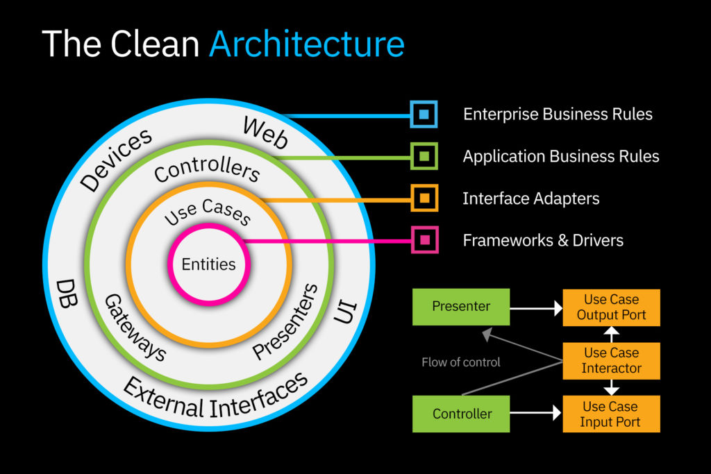
All layers are connected by the dependency rule, which states that in the source code, all dependencies can only be specified internally.
Simply put, nothing from the outer circle can be mentioned by a code from the inner circle. This applies to functions, variables, or any other entity.
Android Mobile App Architecture
Android apps have a complex structure and a typical Android app could contain multiple app components such as services, activities, fragments, content providers and broadcast receivers.
Given that Android apps tend to contain multiple components and that users often interact with multiple apps in a short period of time, apps need to adapt to different kinds of user-driven workflows and tasks.
In addition to this, since it’s possible app components to be launched individually and out-of-order, and the operating system or user can destroy them at any time and these events aren’t under your control, you shouldn’t store any app data or state in your app components, and your app components shouldn’t depend on each other.
If you shouldn’t use app components to store app data and state, how should you design your app?
Essentially, the principles that should guide you include:
- Separations of concerns
- Drive UI from a model
You can read more about Android app architecture here .
iOS Mobile App Architecture
The standard for your iOS mobile app architecture can be easily divided into four layers from bottom to top:
The Core OS Layer (Kernel)
- The Core Services Layer
The Media Layer
- The Cocoa Touch Layer (Interface)l
Learn more about these layers below.
The kernel is the central module of an operating system and is the part of the operating system that loads first and remains in main memory. The kernel is responsible for memory management, process and task management and disk management. It connects the system hardware to the application software. This important layer is in charge of managing memory—allocating and releasing memory once the application has finished with it, taking care of file system tasks, handling networking and other operating system tasks.
Here are some examples of the Core OS layer components:
- OS X Kernel
- BSD (Berkeley Standard Distribution)
- Power Management
- Certificates
- File System
Core Services Layer
The core services layer provides an abstraction over the services provided in the Core OS layer. It provides fundamental access to the iPhone OS services, databases and file controls.
The Core Services Layer consists of the following components:
- Collections
- Address Book
- File Access
- Core Location
- Net Services
- Preferences
- URL Utilities
The media layer contains the tools for processing most media formats and provides multimedia services that you can use within your iPhone and other iOS devices.
The media layer is made up of the following components:
- Audio Mixing
- Audio Recording
- Video Playback
- Image Formats: JPG, PNG and TIFF
- Core Animations
Cocoa Touch Layer
The Cocoa-Touch layer provides an abstraction layer to expose the various libraries for programming the iPhone, and other IOS devices. This layer has a plethora of elements for creating mobile interfaces, and also provides the remaining active layers with data coming from the user.
The Cocoa-Touch layer is made up of the following components:
- Multi-Touch Events
- Multi-Touch Controls
- View Hierarchy
- People Picker
- Controllers
- Accelerometer/Gyroscope
- Localisation/Geographical
- Image Picker
iOS Architecture Design Patterns
Now that we understand the components of iOS app architecture, there are a few different patterns for mobile app architecture for iOS devices including:
- Classic MVC (Model-View-Controller)
- Apple’s MVC (Cocoa MVC)
- MVP (Model-View-Presenter)
- MVVM (Model-View-ViewModel)
- MVVM-C (Model-View-ViewModel-Coordinator)
- VIPER (View, Interactor, Presenter, Entity and Router)
The right one for your app will depend on the expertise of the team you have access to and what is right for your app.
At Coderus, we tend to utilise MVVM and MVVM-C for a few reasons:
- It has a clear separation of concerns.
- Code is easy to follow, understand and maintain.
- ViewModels are very testable.
- Decoupling navigation logic as well as business logic from view code means we avoid having massive view controllers (a common problem in MVC).
- MVVM makes collaboration on code much easier as things are separated nicely.
- We use the coordinator pattern to separate all navigation code from each view controller. This avoids tight coupling between views.
Enterprise Mobile App Architecture
For the smoothest functioning of one’s businesses, many companies use corporate applications that make it effortless for the client and employees to communicate with the company. Inside an application; purchases, communication, and the filtering of services and products from the company are used.
For a modern business, one of the most critical priorities is the strategic use of IT technologies and the addition of business objectives to gain a competitive advantage in the software market.
Likewise, in the enterprise mobile app architecture, there is often a known discrepancy between the IT infrastructure and a company’s business requirements, which is caused by unpredictable and rapid market changes.
The obstacles most commonly ran into in this scenario are most often associated with insufficient speed and low scalability, unreliability, and most importantly the complexity of updating and maintaining software when needed.
Mobile Application Architecture Best Practices
The best practices you need to consider when designing and developing your mobile app architecture include:
- Separation of Concerns: Separate components of your mobile application into distinct sections such that each section addresses a separate concern.
- Single Responsibility Principle: The Single Responsibility Principle states that each component or a module should be responsible for only a specific feature or functionality.
- The Law of Demeter: The Law of Demeter (or the Principle of Least Knowledge) is a design guideline for developing software applications and states that an object should never know the internal details of other objects.
- Don’t Repeat Yourself (DRY). There should be only one component providing a specific functionality; the functionality should not be duplicated in any other component. Don’t repeat yourself is a principle of software development aimed at reducing repetition of software patterns, replacing it with abstractions or using data normalisation to avoid redundancy.
- DO NOT DO BDUF (Big Design Up Front): If your application is an MVP and requirements are unclear, or if there is a possibility of the design evolving over time, avoid making a large design effort too early.
- Composition Over Inheritance: Wherever possible, use composition over inheritance when reusing functionality because inheritance increases the dependency between parent and child classes, thereby limiting the reuse of child classes.
Mobile Application Architecture Checklist
A well-designed architecture is needed for all applications, both the complex ones and the simple. Using the proper architecture for a mobile application not only saves time, but it will also save money and stress.
Want to know if an application project you are working on has solid mobile architecture?
Here is the checklist of questions you need to ask yourself:
- Efficiency: Does the application perform the tasks and functions in any condition? Is the system of the app effective, reliable and copes with all the loads?
- Flexibility: Is the chosen solution simple to change on command with few errors being made? Dynamically, can one element change and it not negatively impact and influence other elements in any negative way?
- Extensibility: Can you add as many functions as you wish to the application?
- Scalability: Has the time for development and updates decreased and does its solid architecture allow you to direct development in parallel threads?
- Testability: Is the architecture for your mobile application easily tested? If so, this means that the number of errors will dramatically decrease from bugs and glitches being discovered and repaired.
- Understandability: Is your code simple to understand in the eyes of all developers? If a lot of people are working on the application leaving notes or a log can be advantageous to the project and a good architecture allows beginners to understand the project quickly.
Key Steps to Choosing Right Architecture for Mobile App
Conduct user research .
User research can cover a wide range of commonly used methods and practice. It can entail anything from doing ethnographic interviews with a niche target group to a classical usability study.
One thing to remember is all user research, regardless of how it is performed, helps place people at the centre of your design process and your line of products. You can use user research to inspire your future designs or use the helpful data captured to measure your impact and adjust accordingly.
User research can often be divided into what’s called quantitative and qualitative methods.
- Surveys and classic market research are examples of quantitative research tools. Quantitative user research methods are meant to measure user behaviour in a way that can then be quantified and used for current and future statistical analysis.
- Interviews and most usability tests are perfect examples of qualitative research tools. These are often more open-ended, hands-on and seek to get an in-depth understanding of the experiences and everyday lives of individual users or user groups.
Each research method has its key advantages and drawbacks. That being said, each can be used for achieving your different goals in mind.
Which method in which you choose will particularly depend on what you want to achieve and will help guide the UX and UI decisions being made for your app.
Other factors and practical concerns will populate as expected, such as what type of project you are currently working on. Your budget and your time constraints can play a role in this decision as well. With that in mind, let’s look at some different reasons for why you should involve users in your design process.
Develop MVP Feature Sets
MVP stands for minimum viable product.
Well, what does that mean?
For any company that is involved in mobile app development, you must try out any new ideas to stay ahead of your competition.
MVP is an essential and helpful tool that finds out the likely response of the audience to the newly launched app. The enormous data collected in this process could be analysed to improve the app further.
The most incredible part of MVP is that you can either release your freshly developed app to a certain number of selected customers or directly launch it freely into the market. This action gives you the flexibility of evaluating the engagement and effectiveness of your application, whether completed or in beta, with your select audience or a large number of people.
Polish Key Functionality
Once you have finished the leading preparations and the reality check, you can turn to work closely with specific platforms and any offline functions. You must reconsider all the benefits and drawbacks of different architecture models and techniques from the standpoint of technical details.
View our comparison of the different types of app development options here covering web vs. native vs. hybrid.
QA Test App
This solution is the bread and butter for intuitive functionality and smoother operation in your project.
With the information about your current users, you can carefully craft a solution that will deeply not only satisfy the needs of the customer but solve any problems that may arise when debugging .
If your users work on various platforms to perform their daily tasks other than Android and iOS, like Linux distro or Playstation’s OS, you can always adopt cross-platform development.
If these two most popular platforms are enough, be safe to work with native app development only.
After making that leading decision, you can develop the main functionality on its basis. Create the environment your customers can only dream about. Whether they truly would love to work offline or maybe just reach interesting content in a feed, have a user-friendly navigation method in place.
And most importantly, don’t forget to check with your users whether they like the application! The use of proper architecture is proven to be closely linked to your app’s ability to satisfy your target audience.
At the end of the day, customers look for convenience. Which means the presence of the home menu, lightning-fast load times, stored content, engaging notifications, and eye candy widgets.
Be positive your app meets all these listed requirements — both audience-specific and general preferences.
Optimise Budget
Once you’ve gathered all the data you need concerning your customer’s preferences and have an idea pool of enhanced features to pull from, you can now calculate the costs.
The successful architecture of the modern mobile application is always an unavoidable balance between the key requirements needed and your ability to cover them with company money.
You can also check all the maintenance and support expenses to have a better idea of what needs revising in future planning. Take another look at the decision on native apps or pushing to multiple platforms, if needed. And, of course, never forget to weigh the benefits of return on investment before making the final decision on your mobile app architecture.
The Key Mobile Application Architecture Principles
As a cheat sheet and for future reference, this guide includes the necessary principles every mobile application architecture should follow. If followed correctly, the launch and life of your application will reap its deserved benefits.
- Portability: Portability is the ability of the system to react to the environmental changes.
- Maintainability: Considering the requirement change due to change in environment i.e. market demand or the ease with which a component can be modified to correct faults, improve performance, or other attributes, there is always a need of maintenance for the mobile applications.
- Manageability: Manageability is how efficiently and easily a software system can be monitored and maintained to keep the system performing, secure, and running smoothly.
- Reusability: Reusability considers the reusability of components and protocols and allows for faster application development and a structured development approach.
- Testability: Testability is the ability for each component to be separately testable as the mobile application needs to undergo a testing process to ensure the consistency of the app under different variables.
- Security: Security and customer data is the major non-functional requirement of the application. The application architecture should be robust enough to completely secure the data consumed and used by the application.
- Performance: Mobile users expect a quick response time from the application specifically compared to desktop/web applications. If the application is taking a long time to display the user’s intent, there will be a loss in customer satisfaction and the app will be uninstalled by users.
Do you want to have the best mobile app architecture?
Well, there you have it! In the beginning, you may have been a little fuzzy on what mobile application architecture is. Now you are a seasoned pro! Using this structure and applying these pro tips will be sure to make your new application a success!
We would love to help even more you with your development journey!
Whether your strategy requires one solution or multiple fixes – we’ve got a variety of services to help you achieve your software goals. You may be an established corporate giant looking for a mobile app, or you might be a start-up needing help outlining your launch strategy. Either way, we are confident we can craft a well-tailored service to meet your needs!
Visit our site today to get started! Let’s work together !

Related Insights

Google I/O 2023 – Summary and 3 Key Takeaways
Dev Technology Highlights from Google I/O 2023
UI and UX Design Trends for 2023
Sign Up for Industry Insights

- Awards & Accreditations
- Our Values, Mission & Vision
- Sustainability
- Meet the Team
- Adastral Women in Tech
- DevelopHER Awards
- Cambridge Wireless
- Innovation Martlesham
- Ipswich Makerspace
- SyncIpswich
- British Science Week
- Coderus Creative Concepts
- Creative Computing Club
- Engaging Education
- Innovate Suffolk
- Embedded IoT
- IoT Development
- IoT App Development
- User Experience (UX Design)
- User Interface (UI) Design
- Android App Development
- iPhone App Development
- Cross Platform App Development
- Native App Development
- Embedded Software Development
- Consultancy
- Agile Project Management
- Quality Assurance & Testing
- Support & Maintenance
- Case Studies
- Agriculture
- Energy & Utilities
- Health & Fitness
- IT & Telecommunications
- Retail & eCommerce
- Banking & Finance
- Charities & Non-Profits
- Education, eLearning & Training
- Food Delivery & Restaurant
- Housing & Construction
- Manufacturing
- Media & Entertainment
- Public Sector
- Professional Services
- Real Estate & Property Management
- Transport & Logistics
- Travel & Hospitality
Layer 6 Presentation Layer
De/Encryption, Encoding, String representation
The presentation layer (data presentation layer, data provision level) sets the system-dependent representation of the data (for example, ASCII, EBCDIC) into an independent form, enabling the syntactically correct data exchange between different systems. Also, functions such as data compression and encryption are guaranteed that data to be sent by the application layer of a system that can be read by the application layer of another system to the layer 6. The presentation layer. If necessary, the presentation layer acts as a translator between different data formats, by making an understandable for both systems data format, the ASN.1 (Abstract Syntax Notation One) used.
OSI Layer 6 - Presentation Layer
The presentation layer is responsible for the delivery and formatting of information to the application layer for further processing or display. It relieves the application layer of concern regarding syntactical differences in data representation within the end-user systems. An example of a presentation service would be the conversion of an EBCDIC-coded text computer file to an ASCII-coded file. The presentation layer is the lowest layer at which application programmers consider data structure and presentation, instead of simply sending data in the form of datagrams or packets between hosts. This layer deals with issues of string representation - whether they use the Pascal method (an integer length field followed by the specified amount of bytes) or the C/C++ method (null-terminated strings, e.g. "thisisastring\0"). The idea is that the application layer should be able to point at the data to be moved, and the presentation layer will deal with the rest. Serialization of complex data structures into flat byte-strings (using mechanisms such as TLV or XML) can be thought of as the key functionality of the presentation layer. Encryption is typically done at this level too, although it can be done on the application, session, transport, or network layers, each having its own advantages and disadvantages. Decryption is also handled at the presentation layer. For example, when logging on to bank account sites the presentation layer will decrypt the data as it is received.[1] Another example is representing structure, which is normally standardized at this level, often by using XML. As well as simple pieces of data, like strings, more complicated things are standardized in this layer. Two common examples are 'objects' in object-oriented programming, and the exact way that streaming video is transmitted. In many widely used applications and protocols, no distinction is made between the presentation and application layers. For example, HyperText Transfer Protocol (HTTP), generally regarded as an application-layer protocol, has presentation-layer aspects such as the ability to identify character encoding for proper conversion, which is then done in the application layer. Within the service layering semantics of the OSI network architecture, the presentation layer responds to service requests from the application layer and issues service requests to the session layer. In the OSI model: the presentation layer ensures the information that the application layer of one system sends out is readable by the application layer of another system. For example, a PC program communicates with another computer, one using extended binary coded decimal interchange code (EBCDIC) and the other using ASCII to represent the same characters. If necessary, the presentation layer might be able to translate between multiple data formats by using a common format. Wikipedia
- Data conversion
- Character code translation
- Compression
- Encryption and Decryption
The Presentation OSI Layer is usually composed of 2 sublayers that are:
CASE common application service element
| ACSE | Association Control Service Element |
|---|---|
| ROSE | Remote Operation Service Element |
| CCR | Commitment Concurrency and Recovery |
| RTSE | Reliable Transfer Service Element |
SASE specific application service element
| FTAM | File Transfer, Access and Manager |
|---|---|
| VT | Virtual Terminal |
| MOTIS | Message Oriented Text Interchange Standard |
| CMIP | Common Management Information Protocol |
| JTM | Job Transfer and Manipulation |
| MMS | Manufacturing Messaging Service |
| RDA | Remote Database Access |
| DTP | Distributed Transaction Processing |
Layer 7 Application Layer
Layer 6 presentation layer, layer 5 session layer, layer 4 transport layer, layer 3 network layer, layer 2 data link layer, layer 1 physical layer.
- Stack Overflow for Teams Where developers & technologists share private knowledge with coworkers
- Advertising & Talent Reach devs & technologists worldwide about your product, service or employer brand
- OverflowAI GenAI features for Teams
- OverflowAPI Train & fine-tune LLMs
- Labs The future of collective knowledge sharing
- About the company Visit the blog
Collectives™ on Stack Overflow
Find centralized, trusted content and collaborate around the technologies you use most.
Q&A for work
Connect and share knowledge within a single location that is structured and easy to search.
Get early access and see previews of new features.
OSI model - What's the presentation and session layer for?
So I feel I pretty well understand the application layer, and everything below (and including) the transport layer.
The session and presentation layers, though, I don't fully understand. I've read the simplistic descriptions in Wikipedia, but it doesn't have an example of why separating out those layers is useful.
- What is the session layer? What does it do, and under what circumstances is it better to have a session layer than simply talk to the transport with your app?
- What is the presentation layer? (same questions as above)
7 Answers 7
The session layer is meant to store states between two connections, like what we use cookies for when working with web programming.
The presentation layer is meant to convert between different formats. This was simpler when the only format that was worried about was character encoding, ie ASCII and EBCDIC. When you consider all of the different formats that we have today(Quicktime, Flash, Pdf) centralizing this layer is out of the question.
TCP/IP doesn't make any allocation to these layers, since they are really out of the scope of a networking protocol. It's up to the applications that take advantage of the stack to implement these.
The reasons there aren't any examples on wikipedia is that there aren't a whole lot of examples of the OSI network model, period.
OSI has once again created a standard nobody uses, so nobody really know how one should use it.
Layers 5-6 are not commonly used in today's web applications, so you don't hear much about them. The TCP/IP stack is slightly different than a pure OSI Model.
One of the reasons TCP/IP is used today instead of OSI is it was too bloated and theoretical, the session and presentation layer aren't really needed as separate layers as it turned out.
I think that presentation layer protocols define the format of data. This means protocols like XML or ASN.1. You could argue that video/audio codecs are part of the presentation layer Although this is probably heading towards the application layer.
I can't help you with the session layer. That has always baffled me.
To be honest, there are very vague boundaries in everything above the transport layer. This is because it is usually handled by a single software application. Also, these layers are not directly associated with transporting data from A to B. Layers 4 and below each have a very specific purpose in moving the data e.g. switching, routing, ensuring data integrity etc. This makes it easier to distinguish between these layers.
Presentation Layer The Presentation Layer represents the area that is independent of data representation at the application layer - in general, it represents the preparation or translation of application format to network format, or from network formatting to application format. In other words, the layer “presents” data for the application or the network. A good example of this is encryption and decryption of data for secure transmission - this happens at Layer 6.
Session Layer When two devices, computers or servers need to “speak” with one another, a session needs to be created, and this is done at the Session Layer. Functions at this layer involve setup, coordination (how long should a system wait for a response, for example) and termination between the applications at each end of the session.
For the presentation layer :because most of communication done between heterogeneous systems (Operating Systems,programing langages,cpu architectures)we need to use a unified idepedent specification .like ANS1 ans BRE.
Your Answer
Reminder: Answers generated by artificial intelligence tools are not allowed on Stack Overflow. Learn more
Sign up or log in
Post as a guest.
Required, but never shown
By clicking “Post Your Answer”, you agree to our terms of service and acknowledge you have read our privacy policy .
Not the answer you're looking for? Browse other questions tagged networking model stack osi or ask your own question .
- The Overflow Blog
- From PHP to JavaScript to Kubernetes: how one backend engineer evolved over time
- Featured on Meta
- We've made changes to our Terms of Service & Privacy Policy - July 2024
- Bringing clarity to status tag usage on meta sites
- What does a new user need in a homepage experience on Stack Overflow?
- Feedback requested: How do you use tag hover descriptions for curating and do...
Hot Network Questions
- On page 31 of ISL, why is the minimum possible test MSE over all methods (dashed line) 1 instead of another number?
- Are automorphisms of matrix algebras necessarily determinant preservers?
- Calculate the sum of numbers in a rectangle
- Did US troops insist on segregation in British pubs?
- An integral using Mathematica or otherwise
- Inconsistent “unzip -l … | grep -q …” results with pipefail
- How can I address my colleague communicating with us via chatGPT?
- How is the grammar of this sentence explained?
- Why cant we save the heat rejected in a heat engine?
- Can figere come with a dative?
- Idiomatic alternative to “going to Canossa”
- Why do we reduce a body to it's center of mass when calculating gain/loss of gravitational potential energy?
- How can I draw water level in a cylinder like this?
- Help Identify SMD Part Marking ATPJ
- How can I push back on my co-worker's changes that I disagree with?
- "Authorized ESTA After Incorrectly Answering Criminal Offense Question: What Should I Do?"
- Video game where the hero gets transported to another world with his sister to aid a king in a war
- Is there racial discrimination at Tbilisi airport?
- Is the error in translation of Genesis 19:5 deliberate?
- When a submarine blows its ballast and rises, where did the energy for the ascent come from?
- Remove lines from a table
- Cannot find where \IfPackageLoadedTF described
- High CPU Usage by Unknown Process with Garbled Command Name on Linux Server – Potential Trojan?
- Which game is "that 651"?
Application Architecture Guide - Chapter 10 - Presentation Layer Guidelines
Note - The patterns & practices Microsoft Application Architecture Guide, 2nd Edition is now live at http://msdn.microsoft.com/en-us/library/dd673617.aspx .
- J.D. Meier, Alex Homer, David Hill, Jason Taylor, Prashant Bansode, Lonnie Wall, Rob Boucher Jr, Akshay Bogawat
- 1 Objectives
- 3 Presentation Layer Components
- 5 Design Considerations
- 6 Presentation Layer Frame
- 8 Composition
- 9 Exception Management
- 12 Navigation
- 13 Presentation Entities
- 14 Request Processing
- 15 User Experience
- 16 UI Components
- 17 UI Process Components
- 18 Validation
- 19 Pattern Map
- 20 Pattern Descriptions
- 21.1 Mobile Applications
- 21.2 Rich Client Applications
- 21.3 Rich Internet Applications (RIA)
- 21.4 Web Applications
- 22 patterns & practices Solution Assets
- 23 Additional Resources
- Understand how the presentation layer fits into typical application architecture.
- Understand the components of the presentation layer.
- Learn the steps for designing the presentation layer.
- Learn the common issues faced while designing the presentation layer.
- Learn the key guidelines for designing the presentation layer.
- Learn the key patterns and technology considerations for designing the presentation layer.
The presentation layer contains the components that implement and display the user interface and manage user interaction. This layer includes controls for user input and display, in addition to components that organize user interaction. Figure 1 shows how the presentation layer fits into a common application architecture.

Figure 1 A typical application showing the presentation layer and the components it may contain
Presentation Layer Components
- User interface (UI) components . User interface components provide a way for users to interact with the application. They render and format data for users. They also acquire and validate data input by the user.
- User process components . User process components synchronize and orchestrate user interactions. Separate user process components may be useful if you have a complicated UI. Implementing common user interaction patterns as separate user process components allows you to reuse them in multiple UIs.
The following steps describe the process you should adopt when designing the presentation layer for your application. This approach will ensure that you consider all of the relevant factors as you develop your architecture:
- Identify your client type . Choose a client type that satisfies your requirements and adheres to the infrastructure and deployment constraints of your organization. For instance, if your users are on mobile devices and will be intermittently connected to the network, a mobile rich client is probably your best choice.
- Determine how you will present data . Choose the data format for your presentation layer and decide how you will present the data in your UI.
- Determine your data-validation strategy . Use data-validation techniques to protect your system from untrusted input.
- Determine your business logic strategy . Factor out your business logic to decouple it from your presentation layer code.
- Determine your strategy for communication with other layers . If your application has multiple layers, such as a data access layer and a business layer, determine a strategy for communication between your presentation layer and other layers.
Design Considerations
There are several key factors that you should consider when designing your presentation layer. Use the following principles to ensure that your design meets the requirements for your application, and follows best practices:
- Choose the appropriate UI technology. Determine if you will implement a rich (smart) client, a Web client, or a rich Internet application (RIA). Base your decision on application requirements, and on organizational and infrastructure constraints.
- Use the relevant patterns. Review the presentation layer patterns for proven solutions to common presentation problems.
- Design for separation of concerns. Use dedicated UI components that focus on rendering and display. Use dedicated presentation entities to manage the data required to present your views. Use dedicated UI process components to manage the processing of user interaction.
- Consider human interface guidelines. Review your organization’s guidelines for UI design. Review established UI guidelines based on the client type and technologies that you have chosen.
- Adhere to user-driven design principles. Before designing your presentation layer, understand your customer. Use surveys, usability studies, and interviews to determine the best presentation design to meet your customer’s requirements.
Presentation Layer Frame
There are several common issues that you must consider as your develop your design. These issues can be categorized into specific areas of the design. The following table lists the common issues for each category where mistakes are most often made.
Table 1 Presentation Layer Frame
| * Caching volatile data. | |
| * Failing to consider use of patterns and libraries that support dynamic layout and injection of views and presentation at runtime. | |
| * Failing to catch unhandled exceptions. | |
| * Failing to design for intuitive use, or implementing overly complex interfaces. | |
| * Using an inappropriate layout style for Web pages. | |
| * Inconsistent navigation. | |
| * Defining entities that are not necessary. | |
| * Blocking the UI during long-running requests. | |
| * Displaying unhelpful error messages. | |
| * Creating custom components that are not necessary. | |
| * Implementing UI process components when not necessary. | |
| * Failing to validate all input. |
Caching is one of the best mechanisms you can use to improve application performance and UI responsiveness. Use data caching to optimize data lookups and avoid network round trips. Cache the results of expensive or repetitive processes to avoid unnecessary duplicate processing.
Consider the following guidelines when designing your caching strategy:
- Do not cache volatile data.
- Consider using ready-to-use cache data when working with an in-memory cache. For example, use a specific object instead of caching raw database data.
- Do not cache sensitive data unless you encrypt it.
- If your application is deployed in Web farm, avoid using local caches that need to be synchronized; instead, consider using a transactional resource manager such as Microsoft SQL Server® or a product that supports distributed caching.
- Do not depend on data still being in your cache. It may have been removed.
Composition
Consider whether your application will be easier to develop and maintain if the presentation layer uses independent modules and views that are easily composed at run time. Composition patterns support the creation of views and the presentation layout at run time. These patterns also help to minimize code and library dependencies that would otherwise force recompilation and redeployment of a module when the dependencies change. Composition patterns help you to implement sharing, reuse, and replacement of presentation logic and views.
Consider the following guidelines when designing your composition strategy:
- Avoid using dynamic layouts. They can be difficult to load and maintain.
- Be careful with dependencies between components. For example, use abstraction patterns when possible to avoid issues with maintainability.
- Consider creating templates with placeholders. For example, use the Template View pattern to compose dynamic Web pages in order to ensure reuse and consistency.
- Consider composing views from reusable modular parts. For example, use the Composite View pattern to build a view from modular, atomic component parts.
- If you need to allow communication between presentation components, consider implementing the Publish/Subscribe pattern. This will lower the coupling between the components and improve testability.
Exception Management
Design a centralized exception-management mechanism for your application that catches and throws exceptions consistently. Pay particular attention to exceptions that propagate across layer or tier boundaries, as well as exceptions that cross trust boundaries. Design for unhandled exceptions so they do not impact application reliability or expose sensitive information.
Consider the following guidelines when designing your exception management strategy:
- Use user-friendly error messages to notify users of errors in the application.
- Avoid exposing sensitive data in error pages, error messages, log files, and audit files.
- Design a global exception handler that displays a global error page or an error message for all unhandled exceptions.
- Differentiate between system exceptions and business errors. In the case of business errors, display a user-friendly error message and allow the user to retry the operation. In the case of system exceptions, check to see if the exception was caused by issues such as system or database failure, display a user-friendly error message, and log the error message, which will help in troubleshooting.
- Avoid using exceptions to control application logic.
Design a user input strategy based on your application input requirements. For maximum usability, follow the established guidelines defined in your organization, and the many established industry usability guidelines based on years of user research into input design and mechanisms.
Consider the following guidelines when designing your input collection strategy:
- Use forms-based input controls for normal data-collection tasks.
- Use a document-based input mechanism for collecting input in Microsoft Office–style documents.
- Implement a wizard-based approach for more complex data collection tasks, or for input that requires a workflow.
- Design to support localization by avoiding hard-coded strings and using external resources for text and layout.
- Consider accessibility in your design. You should consider users with disabilities when designing your input strategy; for example, implement text-to-speech software for blind users, or enlarge text and images for users with poor sight. Support keyboard-only scenarios where possible for users who cannot manipulate a pointing device.
Design your UI layout so that the layout mechanism itself is separate from the individual UI components and UI process components. When choosing a layout strategy, consider whether you will have a separate team of designers building the layout, or whether the development team will create the UI. If designers will be creating the UI, choose a layout approach that does not require code or the use of development-focused tools.
Consider the following guidelines when designing your layout strategy:
- Use templates to provide a common look and feel to all of the UI screens.
- Use a common look and feel for all elements of your UI to maximize accessibility and ease of use.
- Consider device-dependent input, such as touch screens, ink, or speech, in your layout. For example, with touch-screen input you will typically use larger buttons with more spacing between them than you would with mouse or keyboard inputs.
- When building a Web application, consider using Cascading Style Sheets (CSS) for layout. This will improve rendering performance and maintainability.
- Use design patterns, such as Model-View-Presenter (MVP), to separate the layout design from interface processing.
Design your navigation strategy so that users can navigate easily through your screens or pages, and so that you can separate navigation from presentation and UI processing. Ensure that you display navigation links and controls in a consistent way throughout your application to reduce user confusion and hide application complexity.
Consider the following guidelines when designing your navigation strategy:
- Use well-known design patterns to decouple the UI from the navigation logic where this logic is complex.
- Design toolbars and menus to help users find functionality provided by the UI.
- Consider using wizards to implement navigation between forms in a predictable way.
- Determine how you will preserve navigation state if the application must preserve this state between sessions.
- Consider using the Command Pattern to handle common actions from multiple sources.
Presentation Entities
Use presentation entities to store the data you will use in your presentation layer to manage your views. Presentation entities are not always necessary; use them only if your datasets are sufficiently large and complex to require separate storage from the UI controls.
Consider the following guidelines when designing presentation entities:
- Determine if you require presentation entities. Typically, you may require presentation entities only if the data or the format to be displayed is specific to the presentation layer.
- If you are working with data-bound controls, consider using custom objects, collections, or datasets as your presentation entity format.
- If you want to map data directly to business entities, use a custom class for your presentation entities.
- Do not add business logic to presentation entities.
- If you need to perform data type validation, consider adding it in your presentation entities.
Request Processing
Design your request processing with user responsiveness in mind, as well as code maintainability and testability.
Consider the following guidelines when designing request processing:
- Use asynchronous operations or worker threads to avoid blocking the UI for long-running actions.
- Avoid mixing your UI processing and rendering logic.
- Consider using the Passive View pattern (a variant of MVP) for interfaces that do not manage a lot of data.
- Consider using the Supervising Controller pattern (a variant of MVP) for interfaces that manage large amounts of data.
User Experience
Good user experience can make the difference between a usable and unusable application. Carry out usability studies, surveys, and interviews to understand what users require and expect from your application, and design with these results in mind.
Consider the following guidelines when designing for user experience:
- When developing a rich Internet application (RIA), avoid synchronous processing where possible.
- When developing a Web application, consider using Asynchronous JavaScript and XML (AJAX) to improve responsiveness and to reduce post backs and page reloads.
- Do not design overloaded or overly complex interfaces. Provide a clear path through the application for each key user scenario.
- Design to support user personalization, localization, and accessibility.
- Design for user empowerment. Allow the user to control how he or she interacts with the application, and how it displays data to them.
UI Components
UI components are the controls and components used to display information to the user and accept user input. Be careful not to create custom controls unless it is necessary for specialized display or data collection.
Consider the following guidelines when designing UI components:
- Take advantage of the data-binding features of the controls you use in the UI.
- Create custom controls or use third-party controls only for specialized display and data-collection tasks.
- When creating custom controls, extend existing controls if possible instead of creating a new control.
- Consider implementing designer support for custom controls to make it easier to develop with them.
- Consider maintaining the state of controls as the user interacts with the application instead of reloading controls with each action.
UI Process Components
UI process components synchronize and orchestrate user interactions. UI processing components are not always necessary; create them only if you need to perform significant processing in the presentation layer that must be separated from the UI controls. Be careful not to mix business and display logic within the process components; they should be focused on organizing user interactions with your UI.
Consider the following guidelines when designing UI processing components:
- Do not create UI process components unless you need them.
- If your UI requires complex processing or needs to talk to other layers, use UI process components to decouple this processing from the UI.
- Consider dividing UI processing into three distinct roles: Model, View, and Controller/Presenter, by using the MVC or MVP pattern.
- Avoid business rules, with the exception of input and data validation, in UI processing components.
- Consider using abstraction patterns, such as dependency inversion, when UI processing behavior needs to change based on the run-time environment.
- Where the UI requires complex workflow support, create separate workflow components that use a workflow system such as Windows Workflow or a custom mechanism.
Designing an effective input and data-validation strategy is critical to the security of your application. Determine the validation rules for user input as well as for business rules that exist in the presentation layer.
Consider the following guidelines when designing your input and data validation strategy:
- Validate all input data on the client side where possible to improve interactivity and reduce errors caused by invalid data.
- Do not rely on client-side validation only. Always use server-side validation to constrain input for security purposes and to make security-related decisions.
- Design your validation strategy to constrain, reject, and sanitize malicious input.
- Use the built-in validation controls where possible, when working with .NET Framework.
- In Web applications, consider using AJAX to provide real-time validation.
Pattern Map
Key patterns are organized by key categories, as detailed in the Presentation Layer Frame in the following table. Consider using these patterns when making design decisions for each category.
Table 2 Pattern Map
| * Cache Dependency | |
| * Composite View | |
| * Exception Shielding | |
| * Template View | |
| * Front Controller | |
| * Entity Translator | |
| * Asynchronous Callback | |
| * Model-View-Controller (MVC) |
- For more information on the Page Cache pattern, see “Enterprise Solution Patterns Using Microsoft .NET” at http://msdn.microsoft.com/en-us/library/ms998469.aspx
- For more information on the Model-View-Controller (MVC), Page Controller, Front Controller, Template View, Transform View, and Two-Step View patterns, see “Patterns of Enterprise Application Architecture (P of EAA)” at http://martinfowler.com/eaaCatalog/
- For more information on the Composite View, Supervising Controller, and Presentation Model patterns, see “Patterns in the Composite Application Library” at http://msdn.microsoft.com/en-us/library/cc707841.aspx
- For more information on the Chain of responsibility and Command pattern, see “data & object factory” at http://www.dofactory.com/Patterns/Patterns.aspx
- For more information on the Asynchronous Callback pattern, see “Creating a Simplified Asynchronous Call Pattern for Windows Forms Applications” at http://msdn.microsoft.com/en-us/library/ms996483.aspx
- For more information on the Exception Shielding and Entity Translator patterns, see “Useful Patterns for Services” at http://msdn.microsoft.com/en-us/library/cc304800.aspx
Pattern Descriptions
- Asynchronous Callback. Execute long-running tasks on a separate thread that executes in the background, and provide a function for the thread to call back into when the task is complete.
- Cache Dependency. Use external information to determine the state of data stored in a cache.
- Chain of Responsibility. Avoid coupling the sender of a request to its receiver by giving more than one object a chance to handle the request.
- Composite View . Combine individual views into a composite representation.
- Command Pattern. Encapsulate request processing in a separate command object with a common execution interface.
- Entity Translator. An object that transforms message data types into business types for requests, and reverses the transformation for responses.
- Exception Shielding. Prevent a service from exposing information about its internal implementation when an exception occurs.
- Front Controller . Consolidate request handling by channeling all requests through a single handler object, which can be modified at run time with decorators.
- Model-View-Controller . Separate the UI code into three separate units: Model (data), View (interface), and Presenter (processing logic), with a focus on the View. Two variations on this pattern include Passive View and Supervising Controller, which define how the View interacts with the Model.
- Page Cache. Improve the response time for dynamic Web pages that are accessed frequently but change less often and consume a large amount of system resources to construct.
- Page Controller . Accept input from the request and handle it for a specific page or action on a Web site.
- Passive View . Reduce the view to the absolute minimum by allowing the controller to process user input and maintain the responsibility for updating the view.
- Presentation Model . Move all view logic and state out of the view, and render the view through data-binding and templates.
- Supervising Controller . A variation of the MVC pattern in which the controller handles complex logic, in particular coordinating between views, but the view is responsible for simple view-specific logic.
- Template View . Implement a common template view, and derive or construct views using this template view.
- Transform View . Transform the data passed to the presentation tier into HTML for display in the UI.
- Two-Step View . Transform the model data into a logical presentation without any specific formatting, and then convert that logical presentation to add the actual formatting required.
Technology Considerations
The following guidelines will help you to choose an appropriate implementation technology. The guidelines also contain suggestions for common patterns that are useful for specific types of application and technology.
Mobile Applications
Consider the following guidelines when designing a mobile application:
- If you want to build full-featured connected, occasionally connected, and disconnected executable applications that run on a wide range of Microsoft Windows®–based devices, consider using the Microsoft Windows Compact Framework.
- If you want to build connected applications that require Wireless Application Protocol (WAP), compact HTML (cHTML), or similar rendering formats, consider using ASP.NET Mobile Forms and Mobile Controls.
- If you want to build applications that support rich media and interactivity, consider using Microsoft Silverlight® for Mobile.
Rich Client Applications
Consider the following guidelines when designing a rich client application:
- If you want to build applications with good performance and interactivity, and have design support in Microsoft Visual Studio®, consider using Windows Forms.
- If you want to build applications that fully support rich media and graphics, consider using Windows Presentation Foundation (WPF).
- If you want to build applications that are downloaded from a Web server and then execute on the client, consider using XAML Browser Applications (XBAP).
- If you want to build applications that are predominantly document-based, or are used for reporting, consider designing a Microsoft Office Business Application.
- If you decide to use Windows Forms and you are designing composite interfaces, consider using the Smart Client Software Factory.
- If you decide to use WPF and you are designing composite interfaces, consider using the Composite Application Guidance for WPF.
- If you decide to use WPF, consider using the Presentation Model (Model-View-ViewModel) pattern.
- If you decide to use WPF, consider using WPF Commands to communicate between your View and your Presenter or ViewModel.
- If you decide to use WPF, consider implementing the Presentation Model pattern by using DataTemplates over User Controls to give designers more control.
Rich Internet Applications (RIA)
Consider the following guidelines when designing an RIA:
- If you want to build browser-based, connected applications that have broad cross-platform reach, are highly graphical, and support rich media and presentation features, consider using Silverlight.
- If you decide to use Silverlight, consider using the Presentation Model (Model-View-ViewModel) pattern.
Web Applications
Consider the following guidelines when designing a Web application:
- If you want to build applications that are accessed through a Web browser or specialist user agent, consider using ASP.NET.
- If you want to build applications that provide increased interactivity and background processing, with fewer page reloads, consider using ASP.NET with AJAX.
- If you want to build applications that include islands of rich media content and interactivity, consider using ASP.NET with Silverlight controls.
- If you are using ASP.NET and want to implement a control-centric model with separate controllers and improved testability, consider using the ASP.NET MVC Framework.
- If you are using ASP.NET, consider using master pages to simplify development and implement a consistent UI across all pages.
patterns & practices Solution Assets
- Web Client Software Factory at http://msdn.microsoft.com/en-us/library/bb264518.aspx
- Smart Client Software Factory at http://msdn.microsoft.com/en-us/library/aa480482.aspx
- Composite Application Guidance for WPF at http://msdn.microsoft.com/en-us/library/cc707819.aspx
- Smart Client - Composite UI Application Block at http://msdn.microsoft.com/en-us/library/aa480450.aspx
Additional Resources
- For more information, see Microsoft Inductive User Interface Guidelines at http://msdn.microsoft.com/en-us/library/ms997506.aspx .
- For more information, see User Interface Control Guidelines at http://msdn.microsoft.com/en-us/library/bb158625.aspx .
- For more information, see User Interface Text Guidelines at http://msdn.microsoft.com/en-us/library/bb158574.aspx .
- For more information, see Design and Implementation Guidelines for Web Clients at http://msdn.microsoft.com/en-us/library/ms978631.aspx .
- For more information, see Web Presentation Patterns at http://msdn.microsoft.com/en-us/library/ms998516.aspx .
Navigation menu
Page actions.
- View source
Personal tools
- Community portal
- Current events
- Recent changes
- Random page
- What links here
- Related changes
- Special pages
- Printable version
- Permanent link
- Page information
- This page was last edited on 22 January 2010, at 07:50.
- Privacy policy
- About Guidance Share
- Disclaimers
- MVP Development
- Custom Software Development
- Web Application Development
- Backend Development
- Mobile Application Development
- Application Modernization
- Software Project Rescue
- Performance Analysis
- Maintenance and Support
- Telecom Systems Integration
- Marketing & Ad
- Agriculture
- Shopify store
- Live streaming
- Real-time communication
- Case Studies
Mobile App Architecture: How to Choose the Right One?
- Mobile App Architecture: How to…
 (1)")
Introduction
We may argue that mobile apps are the main focus of the corporate world, based on global market conditions and user behaviour.
Because of the Covid-19 pandemic, applications began to take up more room in people’s lives, particularly in recent years. According to Statista , global revenue from mobile apps would exceed $488 billion by 2023. This figure is estimated to exceed $611.54 billion by 2026. As of the third quarter of 2022, the number of applications available on Google Play, the Apple App Store, and the Amazon Appstore has almost reached 5.7 million apps.
As a result, you cannot overlook the significance and growing influence of mobile apps. The way you develop and design your mobile app will be critical to the success of your company. In other words, to succeed in this challenging digital arena, you must understand the concept of app architecture inside and out.
Why is Good Mobile App Architecture Important?
When developing a mobile or web app, you should ensure that each component is well-built. Even minor issues that may arise during the process of developing a mobile application architecture can degrade the end product’s quality. If you want to do something, do it well, as the saying goes. As a result, most popular Android and iOS apps have a very stable architecture and successfully attract users.
So, what is the definition of mobile app architecture? It is a collection of structural components and their interfaces that make up the system, as well as their behaviour within the framework of all such elements. This is the backbone of a program, and its quality determines the entire work of the mobile application.
You threaten the success of your project by overlooking a key component of developing a mobile apps architecture. And remember that the complexity of a high-quality architecture is proportional to the size of the application. In the future, when the software requires maintenance and updates, effective architecture will allow for significant savings in time, energy, and expenses.
If the app is built without architecture, it may have several undesirable consequences. These include increased development costs and extended processes, issues with application testing and maintenance, increased error risks, and so on.
What factors contribute to a successful architecture of mobile application?
A well-matched architecture of a mobile app can make a significant difference. It may fully reinforce and expedite software development processes, as well as provide a clear way for data flow, making future scaling easier. The right structure can also enable greater flexibility and the use of Agile development methodologies.
As a result, testing processes will become more straightforward and efficient, and further app support will be streamlined. So a mobile application architecture will greatly save your business time and money.
A Mobile App Architecture Diagram
To begin with, having a proper architecture ensures that your application won’t have to always rely on external resources. Architecture should be independent of the availability of any library. So you should aim to utilise frameworks as tools rather than force your system to conform to their constraints. Your mobile application architecture should not be visible to other operating systems or databases for it to function, and it must operate regardless of the state of other apps.
Clean Architecture, for example, is suitable for big projects with huge budgets. This style of design is flexible, allowing for the installation of numerous plug-ins as well as rapid debugging, but it should not be built with frameworks. The computer code must be written from the ground up.
Consider the following example of an effectively developed mobile application architecture:

The Clean architecture is typically presented as a circle with four layers:
- Entities represent business logic;
- Use Cases represent app logic;
- Adapters transfer data from the use cases format to an external agency format, such as a database or the web;
- Frameworks and Drivers represent the outer layer that is made up of frameworks and tools such as databases, user interfaces, HTTP clients, and so on.
Each layer of such a mobile app is self-contained and holds a key piece of your application’s logic as well as important objects. The Dependency Rule, which specifies that all dependencies can only be expressed internally in the source code, connects all layers. Nothing from the outer circle, for example, can be mentioned by a code from the inner circle. This is true for functions, classes, variables, and any other type of entity.
Android Mobile App Architecture
There is no such thing as a single mobile architecture for Android, and Google provides no architecture documentation or recommendations regarding it. Nonetheless, the Android development community has concluded via trial and error that the Clean architecture is the best fit for Android applications.
As was previously mentioned, the separation of architecture layers is what makes Clean architecture so beneficial for Android app development. It makes layers independent while still allowing them to exchange data.
In today’s world, using Clean Architecture is the greatest way for ensuring dependable operation. This architecture will let your application be free of frameworks, databases, and other dependencies.
Transitions between layers in this Android mobile app design are accomplished using Boundaries, that is, via two interfaces: one for the request and one for the response. They are required so that the inner layer does not rely on the outer layer (as per the Dependency Rule), but can also communicate data to it.
The notion of dependency inversion is used to guide a dependency in this kind of mobile app design towards the reverse flow of data. That is, rather than being dependent solely on the Presenter, mentioned in the architecture diagram (which would break the Dependency Rule), Use Cases depend on the interface in its layer, which the Presenter must implement.
iOS Mobile App Architecture
Unlike Android, the Apple system provides more assistance to software developers on how to create an iOS mobile structure that is based on the MVC paradigm (Model-View-Controller). However, iOS devs are not confined to just one architectural design; this is simply the one that is most typically used in iOS apps.
The MVC model consists of three layers:
- Model – a data layer that includes persistence, model objects, parsers, managers, and networking code;
- View – is in charge of visual representation. This layer interacts with users and lacks domain-specific logic, thus the classes in this layer are reusable;
- Controller – the layer that facilitates interaction between the view and the model.
The MVC working concept is straightforward. The user interacts with the iOS app and performs a view layer action. The action is passed to the controller via the view. The controller examines the action received and makes certain decisions. If necessary, it can navigate to the Model and make modifications there. The model modifies data values and returns them to the controller. The controller then passes the values to the view, which displays the results to the user.
iOS developers can use the MVC model to:
- Significantly expedite the process of developing mobile apps;
- Create clear communication between app levels;
- Obtain a well-structured, easy-to-maintain codebase;
- Obtain an easy-to-test codebase.
Hybrid Mobile App Architecture
Hybrid mobile apps combine native and web features. Native apps are used as “shells” for the backend of hybrid apps, but platform-neutral JavaScript, HTML, and CSS are used for the frontend. To utilise native platform capabilities, hybrid apps use different plugins such as Apache Cordova or Ionic Capacitor.
Hybrid mobile apps are among the quickest to develop and maintain across several platforms, but they are not suitable for complicated, interactive, or feature-rich applications.

Cross-Platform Mobile App Architecture
Cross-platform architecture of mobile applications is quite similar to hybrid architecture. It also combines the most commonly used codebases with specific platform capabilities in each native shell. It’s worth emphasising that cross-platform application architecture relies on frameworks like React Native and Xamarin rather than web languages. Cross-platform programmes provide a pleasant user experience that is extremely comparable to native applications and hence more appealing. Here are a few advantages of cross-platform architecture:

Enterprise Mobile App Architecture
Many firms utilise corporate applications to ensure their operations run smoothly. These applications make it simple for clients and workers to communicate with the company. Monitoring, purchases, communication, and filtering services, as well as products from the corporation can all be used within the application. One of the goals of a modern corporation is the strategic use of IT technology and the realisation of business objectives to achieve a competitive edge in the market.
At the same time, there is frequently a mismatch between IT infrastructure and business requirements in enterprise architecture of mobile applications, which is driven by quick market changes. The most common issues with the information architecture of business solutions are insufficient speed and limited scalability, unreliability, and the complexity of upgrading and maintaining software.
Properties of Mobile Application Architecture
We already know that using the Clean architecture is suggested for the high-quality, smooth functioning of your mobile application. When developing a suitable platform for the comfort of your clients and staff, you should follow a few guidelines to ensure the best quality of your mobile applications architecture. It is critical to put together the correct technical requirements for the development team so that the experts can work together toward the same goal.
What to Consider Before Developing Mobile App Architecture
Some factors should be considered first of all when creating a solid foundation for a mobile app. Specifically, developing a mobile app necessitates foresight in four crucial dimensions:
- Choosing the mobile app dimensions that are compatible with your preferred devices;
- Creating scenarios for various Internet connection quality levels;
- UI refinement for your target audience;
- Choosing the best way to navigate between elements on a screen.
Determine the Device Types
At this point, you must take the device type into account. This would necessitate investigating the screen size, resolution, CPU characteristics, RAM, and storage space, as well as the availability of the environment of the development tool.
The app’s functionalities would be dependent on the software or hardware, which is why it is critical to obtain information about the devices on which the app would run.
Bandwidth Scenarios
Throughout its existence, your application may encounter various scenarios when network connection will either be unreliable or non-existent. Your application architecture diagram must be developed with the worst network conditions in mind. You must plan the data access process, caching, and state management based on the worst-case scenarios.
User Interface
The value of UI/UX in an application cannot be overstated. Ensuring that your user interface (UI) is built to keep users interested and provide them with an uncluttered experience is a key component of your mobile application architecture – one that will define how well it is developed.
Navigation Method
The process of designing the navigation elements of the app necessitates knowledge of both the backend and the frontend. Based on your understanding of who your clients are and what their app requirements are, you should decide which of the following would be best for your app:
- Stacked navigation bar — you create a fixed bar and place links to all other items in your mobile app on it;
- Tab controller — a container that facilitates linking between groups of tabs;
- Modal controller — a screen menu that allows you to switch between tabs and links;
- A single view — a screen with only one element and a back button;
- Gesture-based navigation — an easy-to-use feature that encourages users to employ finger combinations or efficiently engage with the Home button to perform a task on the screen.
But knowing these elements will only get you halfway to understanding the concept.

How to Choose the Right Architecture for Your Mobile App?
Everything begins with these key levels when it comes to the intricacies of designing an app:
- The data layer — the platform for data within a mobile app;
- The business layer — the location of all domain procedures and operations;
- The presentation layer — contains all of the technical aspects associated with the user interface.
This multitier architecture dictates the following rule in software development: your team should build each component individually and make them function together nicely. At the same time, this initial principle ensures that complex issues are addressed quickly and without modifying the entire app.
The data layer is responsible for managing data received by the mobile application. This includes data access components, data elements, and functions that allow mobile app activities like data verification to take place. The data layer maintains the accuracy of stored or processed data as long as the app is functioning.
Business Layer
The business layer is concerned with the app’s back-end processes. This layer consists of mobile apps’ logical order and data flow. The business layer covers aspects such as data security and payment gateway solutions. The business layer also controls how the workflow is logically processed, and how the application saves or logs user history.
Presentation Layer
The presentation layer of mobile app architecture describes how well an app is equipped for the optimal user experience or UX design. It combines design components such as visual, auditory, user interface (UI), and navigability to create an appealing aesthetic for the user. Colours, notification sounds, avatars, media, and intuitiveness are all part of the mobile app presentation layer. The presentation layer is equally important in determining how effectively it serves the needs of its targeted end-users as any other layer. The presentation layer, in essence, creates the distinct look and feel of your app architecture.

Steps to Choose the Right Architecture for a Mobile App
Customer research.
To create a successful mobile app, consider your idea as a solution to a specific customer pain point. Find out everything you can about your potential clients: who they are, what apps they use, and what they require. Then consider how you may create a user-friendly mobile app for them. For instance, the older your clientele is, the simpler the style they like. Children appreciate motion design, whilst the elderly are perplexed by it.
Investigate some industry-specific requirements to support your findings. Here, your company’s quirks might help you figure out how your mobile app works. Fashion shops, for example, benefit the most from a web app (where users can see all the product categories and photos in big dimensions). However, taxi services are more convenient to use as a mobile app.
Develop a Test App
Don’t skimp on this stage from the start. Begin by creating native software – this is an excellent solution for intuitive functionality and smooth functioning. Make use of the information you have about your users to design a solution that will deeply satisfy their wants and solve their specific problems.
If your users require platforms other than Android and iOS to complete their duties, consider cross-platform development. If these two most popular platforms are sufficient, stick to native app development.
After making this decision, build the core functionality around it. Create the environment your users want: whether they want to work offline, use a specific navigation strategy, find interesting stuff in a feed, and so on.
And, of course, don’t forget to ask users if they like it! The appropriate architecture is always inextricably tied to your app’s capacity to satisfy your target audience. Finally, users don’t mind improved convenience, which includes the existence of the home menu, notifications, and widgets, as well as fast speed and stored content. Make certain that your app meets all of these standards, both audience-specific and generic preferences.
Key Functionality
After you’ve finished the major preparations and the reality check, you may begin collaborating with specialised platforms and offline functions. This step entails deciding how you will execute the app technically and by particular industry-specific constraints.
First, analyse the advantages and downsides of various architecture models in terms of technical aspects. Native apps, for example, have the best performance and user engagement but require installation and are quite expensive to download. Web apps, on the other hand, are SEO-friendly and do not require installations, but they do require an Internet connection and can perform poorly because of it. Consider Progressive Online Apps (PWAs) as a fantastic compromise – they improve the experience of web apps by increasing stability, engagement, and speed.
Then, ensure that your app has offline capabilities. Users dislike having to rely on their Internet connection while interacting with an app, so give the idea some consideration. Try to move as much of the app’s fundamental functionality as you can offline. Remember that the app has to be native or a PWA to have offline functionality (note that it still depends on the platform). So we propose starting with one of these two mobile app architecture options.
Check the Readiness of Your Development Team
Your company may have some limitations that would hinder the project. You have to assess your team’s capabilities to identify them.
Determine the exact development timeframe for everything. Of course, every entrepreneur wants his or her business idea to become a reality as soon as possible, but your team still requires time to finish it. Thus, before the project begins, talk with your team about whether they have the resources and knowledge required for the frontend and backend development , and how long it would take to complete the project with the current resources.
Pay close attention to their abilities. Knowing such languages as Swift, Objective-C, C, C++, Kotlin, and Java is required if you want to create a native app. HTML, CSS, and Javascript are sufficient for web apps. Also, make sure your staff is familiar with PWAs, hybrid apps (particularly Cordova/PhoneGap and Ionic), and Web Native. If you discover some knowledge gaps, recruit fresh professionals to create the app or begin training the in-house team members.
Budget Optimization
After you’ve gathered all of the information about user preferences, fundamental functions, expanded features, and team constraints, you may compute the expenses. The right architecture of mobile application is always a mix between the primary requirements and your financial capability to cover them.
Examine all of the maintenance and support costs. If necessary, reconsider the decision on native apps against numerous platforms. And, of course, before making the final decision on the architecture of a mobile application, assess the benefits in terms of return on investment.

Final Tips for Your Mobile Architecture
The development of mobile architecture is a step-by-step process that must be finished before the development process can begin. This plan depicts how the application’s various components should be arranged and linked to one another. It binds development to specific rules as well as makes some sacrifices (typically associated with a large number of classes and templates) that will ultimately help you produce a well-written program that is easier to test, expand, and maintain.
Bamboo Agile provides cutting-edge disruptive solutions and data-driven insights to businesses and their workforce. Our team has over 20 years of experience in mobile application development and other types of software development.
Are you and your business ready to alter mindsets and capitalise on innovations? Feel free to reach out to us and book a consultation with our professionals. They are here to help you learn more about the issue and create a solution your company or project is sure to benefit from!
What is the architecture of mobile apps?
The architecture of mobile application is simply a set of principles and practices that are used while designing a mobile app. Following these patterns allows developers to create a well-structured and feature-rich application that adheres to all industry standards and is less prone to faults and failure. The quality of the mobile app architecture determines the project’s success.
Why is this so important for businesses?
A good architecture of a mobile application can not only help you create a good app, but it can also save your company a lot of time and money. Furthermore, a good mobile architecture simplifies app testing and maintenance.
What mobile app architecture to choose to design a top-notch application?
There are several forms of mobile app architecture, including cross-platform, hybrid, and business architecture of mobile application, as well as iOS and Android architecture. It is important to understand your mobile app development goals to select the best one. Define the type of app you want to create — and selecting the best mobile application architecture will be simple.
How useful was this post?
Click on a star to rate it!
We are sorry that this post was not useful for you!
Let us improve this post!
Tell us how we can improve this post?
Author: Anastasia Staver
Writer at Bamboo Agile

Computer Network
- Operating Systems
- Computer Fundamentals
- Interview Q
Physical Layer
Data link layer, network layer, routing algorithm, transport layer, application layer, application protocols, network security.
Interview Questions

| The presentation layer is the 6 layer from the bottom in the OSI model. This layer presents the incoming data from the application layer of the sender machine to the receiver machine. It converts one format of data to another format of data if both sender and receiver understand different formats; hence this layer is also called the translation layer. It deals with the semantics and syntax of the data, so this layer is also called the syntax layer. It uses operations such as data compression, data encryption & decryption, data conversion, etc. Data is sent from sender to receiver, but what if the sender device and receiver device understand different formats of code? For example, suppose one device understands ASCII code and another device understands EBCDIC code. In that case, the data must be translated into a code that the recipient understands to determine what data has been sent. The presentation layer is responsible for translating ASCII codes to EBCDIC or vice versa. With the help of the presentation layer, the receiver understands the data effectively and uses it efficiently. Whatever data is being transmitted between the sender and the receiver, that data must be secure because an intruder can hack the data passing between the sender and the receiver. Hackers can modify the data and send the modified data to the receiver to create false communication. The presentation layer is responsible for encrypting and decrypting data to avoid data leakage and data modification.The plaintext data at the source is encrypted into ciphertext (unreadable format), then it is sent to the receiver, where the ciphertext is decrypted into plaintext. Now, if the hacker tries to hack the data, the hacker receives an encrypted, unreadable form, and if the hacker tries to send modified data, the receiver can detect the modification during decryption; thereby, the data remains safe. If the file size is large, it becomes difficult to transmit the large file over the network. File size can be decreased by compressing the file for easy transmission of data. Compression is the method of diminishing the size of a file to transmit data easily in less time. When the compressed data reaches the receiver, the data is reconstructed back to the original size, and this process is called decompression. The presentation layer in the OSI model is classified into two sublayers: This sublayer offers services to layer-7, i.e., the application layer, and requests services from layer-5, i.e., the session layer. It supports various application services, such as Reliable Transfer Service Element (RTSE), Remote Operation Service Element (ROSE), Association Control Service Element (ACSE), and Commitment Concurrency and Recovery (CCR). This sublayer offers application-specific protocols, such as Message Oriented Text Interchange Standard (MOTIS), Remote Database Access (RDA), File Transfer Access and Manager (FTAM), Common Management Information Protocol (CMIP), Virtual Terminal (VT), Distributed Transaction Processing (DTP), Job Transfer and Manipulation (JTM), and others. It is a presentation layer protocol in the OSI model, which was formed by Citrix Systems. It is used for transferring data from server to client. It is a very thin protocol as it does not require much overhead in order to transmit data from the server over to the client. It is well-optimized for the WAN. It is the protocol that is used to implement the presentation layer of the OSI model. It provides different kinds of data representation, such as images, video, audio, numbers, etc. It is used for Microsoft Remote Procedure Call (Microsoft RPC) and Distributed Computing Environment (DCE) / Remote Procedure Calls (RPC). It is a communication protocol that was specifically designed for macOS by Apple, Inc. It provides file services for Classic Mac OS and macOS. This protocol is used to share files over the network. It is a protocol that is associated with the client-server operating system. The user can access the directory, print, message, file, clock synchronization, etc., with the help of this protocol. It supports many platforms, such as Linux, Classic Mac OS, Windows NT, Mac OS X, and Microsoft Windows. It is a telecommunications equipment that splits a stream of data into separate packets and formats packet headers for asynchronous communication on X.25 networks. It receives packets from the network and converts them into a stream of data. The PAD provides many asynchronous terminal connectivities to a host computer. It is a computer network protocol that is used to transfer data between two systems. It was first published in 1987. XDR is used by various systems such as NDMP, Network File System, NetCDF, ZFS, Open Network Computer Remote Procedure Call, and others. It is a protocol that offers ISO presentation services over TCP/IP based networks. This protocol explains an approach to provide stream-line support for OSI over TCP/IP based networks. |

- Send your Feedback to [email protected]
Help Others, Please Share

Learn Latest Tutorials

Transact-SQL

Reinforcement Learning

R Programming

React Native

Python Design Patterns

Python Pillow

Python Turtle

Preparation

Verbal Ability
Company Questions
Trending Technologies

Artificial Intelligence

Cloud Computing

Data Science

Machine Learning

B.Tech / MCA

Data Structures

Operating System

Compiler Design

Computer Organization

Discrete Mathematics

Ethical Hacking

Computer Graphics

Software Engineering

Web Technology

Cyber Security

C Programming

Control System

Data Mining

Data Warehouse

App Architecture: Presentation layer

This is a series of articles about how to architecture your app that it was inspired by Google Guide to App Architecture and my personal experience.
Today we finally explore the Presentation layer of our architecture. It contains all UI-related logic and everything the user can see and interact with. This layer is also responsible for interpreting application data to the user-readable form and vice versa, transforming user interaction to the data changes in the app.

In this guide, I will demonstrate how to implement and organize a UI layer. There are a lot of libraries, frameworks, and patterns you can use to build a UI layer. Today I’m building everything based on the next tech stack: Android Fragment + Jatpack Compose + Orbit-MVI + Kotlin + Flow + Coroutines + Koin (DI). This is one of the optimal combinations. I will focus on the UI’s building blocks such as Router , Router Container, ViewModel, Screen, and Navigator.
The Route is the main UI unit responsible for:
- Holding ViewModel, Navigator , and Screen composable with UI elements.
- Consuming the UI state.
- Handling Side Effects (one-time action).
- Passing user interaction to the ViewModel .
The main idea that sits behind the Router is to encapsulate and make a self-sustainable UI unit that knows how to produce and manage the UI state (implement unidirectional data flow) and navigate.
Naming conventions
The Route classes are named after the Screen name they’re responsible for.
Screen name + Route.
For example: FareListRoute , ConformationRoute .
| @Composable | |
| fun FareListRoute( | |
| navigator: FareListNavigator, | |
| ryderId: String, | |
| viewModel: FareListViewModel = koinViewModel { parametersOf(ryderId) }, | |
| scaffoldState: ScaffoldState = rememberScaffoldState(), | |
| ) { | |
| val state by viewModel.collectAsState() | |
| FareListScreen( | |
| uiState = state, | |
| scaffoldState = scaffoldState, | |
| onFareClick = viewModel::onFareClick, | |
| ) | |
| viewModel.RenderEffect(scaffoldState = scaffoldState, navigator = navigator) | |
| } | |
| @Composable | |
| private fun FareListViewModel.RenderEffect( | |
| scaffoldState: ScaffoldState, | |
| navigator: FareListNavigator, | |
| ) { | |
| collectSideEffect { effect -> | |
| when (effect) { | |
| is FareListEffect.GoToConfirmation -> { | |
| navigator.goToConfirmation(ryderId = effect.ryderId, fare = effect.fare) | |
| } | |
| FareListEffect.ShowGeneralNetworkError -> scaffoldState.showSnackBar("Network error") | |
| } | |
| } | |
| } |
In the code above you can see what Router looks like. The ViewModel passed as a parameter and injected by Koin (DI). Along with it, we pass Navigator and ryderId as data passed from the previous screen. The one cool feature of the Koin is that you can inject ryderId it into ViewModel the constructor.
The Router can have more than one ViewModel .
I’ll cover it in the section about ViewModel . In the Router we collect the state that ViewModel holds and pass it as a parameter to the Screen .
Do not pass ViewModel as an argument to the Screen composable function. Doing so couples the composable function with the ViewModel type, making it less reusable and harder to test and preview. Also, there would be no clear single source of truth that manages the ViewModel instance.
The collectAsState is extension function ContainerHost that ViewModel implement from the Orbit library.
| @Composable | |
| fun <STATE : Any, SIDE_EFFECT : Any> ContainerHost<STATE, SIDE_EFFECT>.collectAsState( | |
| lifecycleState: Lifecycle.State = Lifecycle.State.STARTED | |
| ): State<STATE> { | |
| return this.collectAsState(lifecycleState) | |
| } |
lifecycleState — The Lifecycle where the restarting collecting from this flow work will be kept alive.
RenderEffect — another extension function (to be able to call ViewModel extension function) responsible for collecting side effects using collectSideEffect .
| @Composable | |
| fun <STATE : Any, SIDE_EFFECT : Any> ContainerHost<STATE, SIDE_EFFECT>.collectSideEffect( | |
| lifecycleState: Lifecycle.State = Lifecycle.State.STARTED, | |
| action: (suspend (sideEffect: SIDE_EFFECT) -> Unit), | |
| ) { | |
| this.collectSideEffect(sideEffect = action, lifecycleState = lifecycleState) | |
| } |
The Side Effect is a one-time action often it’s navigation like GoToConfirmation screen, show Snack Bar, Toast, and Dialog in some cases.
| when (effect) { | |
| is FareListEffect.GoToConfirmation -> { | |
| navigator.goToConfirmation(ryderId = effect.ryderId, fare = effect.fare) | |
| } | |
| FareListEffect.ShowGeneralNetworkError -> scaffoldState.showSnackBar("Network error") | |
| } |
The Router Container
The Fragment is the UI container for Route. It can contain DI-injected fields we don’t want to pass to the Router, and hold arguments.
These classes are named after the UI component that they’re responsible for.
UI component name + Fragment.
For example FareListFragment .
UI component name + Controller.
For example FareListController .
| class FareListFragment : Fragment(R.layout.compose_fragment) { | |
| private val arguments: FareListFragmentArgs by navArgs() | |
| private val navigator: FareListNavigator by inject { | |
| parametersOf(findNavController(), lifecycleScope, requireContext()) | |
| } | |
| override fun onViewCreated(view: View, savedInstanceState: Bundle?) { | |
| super.onViewCreated(view, savedInstanceState) | |
| val composeView = ComposeFragmentBinding.bind(view).compose | |
| setAppComposeContent(composeView) { | |
| FareListRoute(navigator = navigator, ryderId = arguments.ryderId) | |
| } | |
| } | |
| } |
As you can see the code of fragment classes is small because all UI logic is encapsulated in Route, which makes it easy to change the container implementation.
The Router shouldn’t know navigation implementation details, it should depend on Navigator .
That is why the injection logic of the navigator is inside the Fragment, not the Router because the navigator requires a Fragment NavController to implement navigation logic. It keeps the Router decoupled from the container implementation and allows us to easily change container implementation, for example — using Compose navigation or Controller from Conductor lib.
The Navigator is responsible for:
- Encapsulates navigation logic from the Router.
- Restricts navigation API for certain screens.
- Define explicit API for each screen.
If the screen has navigation to another screen, it should have its navigator class. It can be extended from the base ScreenNavigator with a default go-back action, can contain other navigators and platform-dependent components like Fragment NavController .
The navigator classes are named after the Screen name that they’re responsible for:
Screen name + Navigator.
For example FareListNavigator .
Let’s look at the next diagram that shows the relationship between gradle modules of our app.

Here you can see core modules Core , Shared. The f eature modules such as Fare and Profile , and the App module.
For example, we have a Fare module with features and one of them has a button for navigation to the profile screen of the user. The user profile page is in the Profile module. How to implement this navigation?
For that, we need to create an interface ProfileSharedNavigator that knows how to navigate to the user Profile page, and keep it in the Shared module.
| interface ProfileSharedNavigator { | |
| fun goToProfile(userId: String) | |
| } |
According to our architecture, the Fare module depends on Shared, so we can use ProfileSharedNavigator in the FareListNavigator .
| class FareListNavigator( | |
| private val navController: NavController, | |
| private val profileNavigator: ProfileSharedNavigator, | |
| ) : ScreenNavigator(navController) { | |
| fun goToConfirmation(ryderId: String, fare: FareModel) { | |
| navController.navigateSafely( | |
| FareListFragmentDirections.actionFareListFragmentToConfirmationFragment( | |
| ryderId = ryderId, | |
| fare = fare | |
| ) | |
| ) | |
| } | |
| fun goToProfile(userId: String) { | |
| profileNavigator.goToProfile(userId) | |
| } | |
| } |
We pass ProfileSharedNavigator to the FareListNavigator as one of its arguments and delegate navigation calls to it.
The ScreenNavigator is the base class that knows only how to navigate back.
| abstract class ScreenNavigator( | |
| private val navController: NavController | |
| ) { | |
| open fun goBack() { | |
| navController.navigateUp() | |
| } | |
| } |
The App module knows everything about everyone in the app. The main purpose of this module is to organize all dependency injection logic between all feature modules in the project.
| class AppNavigator( | |
| private val navController: NavController, | |
| ) : ProfileSharedNavigator { | |
| override fun goToProfile(userId: String) { | |
| navController.navigateSafely( | |
| FareListFragmentDirections.actionFareListFragmentToProfileFragment(userId) | |
| ) | |
| } | |
| } |
As you can see AppNavigator hold the real implementation of the ProfileSharedNavigator interface. We can depend on this interface across different modules, and create real instances of it in the App module following the Dependency Inversion Principle (DIP) .
The state file contains the UI state data class and for the Side Effects sealed class suites the best. State class can be Parcelable (optional) if you want the state to survive through the configuration changes. All properties should have a default value if it’s possible. Effect class contains one-time action on UI, like navigation, show toast, snack bar, bottom sheet, or dialog. To learn more about Effect you can read Orbit Side Effect documentation.
The state classes are named after the UI component type they’re responsible for. The convention is as follows:
UI component name + State.
UI component name + Effect.
For example: FareListState and FareListEffect .
| @Parcelize | |
| data class FareListState( | |
| val status: ScreenContentStatus = ScreenContentStatus.Idle, | |
| val showRequestLoading: Boolean = false, | |
| val fares: List<FareModel> = emptyList(), | |
| ) : Parcelable | |
| sealed class FareListEffect { | |
| data class GoToConfirmation(val ryderId: String, val fare: FareModel) : FareListEffect() | |
| data object ShowGeneralNetworkError : FareListEffect() | |
| } |
If your screen has different loading states, better to explicitly split it in your state class. The screen can have few content states, such as Idle , Loading , Refreshing , Success , Failure . After the initial content loading, we might want to make a request to the server and show loading to the user, in that case better to show the loading dialog using a separate showRequestLoading property instead of using status a field and set ScreenContentStatus.Loading . The point is not to try to reuse one field to cover different loading cases.
The Presentation layer also has its data models that reflect models from the Domain layer but are more UI-specific. The mapping logic of the presentation model to the domain and vice versa should be placed in the ViewModel class.
| @Parcelize | |
| data class FareModel( | |
| val description: String, | |
| val price: Float, | |
| ) : Parcelable |
Android Auto and ViewModel: Reuse your code in your car!
Flutter clean code and best practices, designing effective compose uis for enhancing previews.
Senior Android Engineer
Senior Android Developer
Our video recommendation, kobweb:creating websites in kotlin leveraging compose html.

Senior Backend Developer
Expert outils et système d’exploitation Android H/F
Senior Android Software Engineer – Native SDKs Application
Team Lead App Development (all genders)
Principal Windows Software Architecture
Backend Engineer – Java/Kotlin (m/f/d)
Senior Cybersecurity Engineer
Uber – Staff Android Engineer, Rider
Senior Full Stack Developer
- The presentation layer shouldn’t expose the UI model to other layers.
- The presentation model can implement platform-specific ways of serialization such as Parcelable and Serializable .
- The presentation model should be immutable.
The model classes are named after the data type that they’re responsible for:
type of data + Model.
For example: Ryder , Fare .
The ViewModel is a business logic state holder. In Android development, ViewModel is suitable for providing access to the business logic and preparing the application data for presentation on the screen. Also, process user events and transform data from the data or domain layers to screen UI state.
For the current implementation, I’m using androidx.lifecycle.ViewModel and Orbit-MVI lib. The ViewModel holds the Orbit container and implements ContainerHost . Check out Orbit API documentation to understand better what going on.
The ViewModel classes are named after the UI component type that they’re responsible for:
UI component name + ViewModel.
For example FareListViewModel .
| class FareListViewModel( | |
| private val exceptionHandler: ExceptionHandler, | |
| private val ryderId: String, | |
| private val getFaresByIdUseCase: GetFaresByIdUseCase, | |
| ) : ViewModel(), ContainerHost<FareListState, FareListEffect> { | |
| override val container: Container<FareListState, FareListEffect> = container( | |
| initialState = FareListState(), | |
| buildSettings = { | |
| this.exceptionHandler = | |
| this@FareListViewModel.exceptionHandler.asCoroutineExceptionHandler() | |
| }, | |
| ) { | |
| fetchFares() | |
| } | |
| private fun fetchFares() = intent { | |
| reduce { state.copy(status = ScreenContentStatus.Loading) } | |
| executeUseCase { getFaresByIdUseCase(ryderId).asPresentation() } | |
| .onSuccess { fares -> | |
| reduce { | |
| state.copy( | |
| status = ScreenContentStatus.Success, | |
| fares = fares | |
| ) | |
| } | |
| } | |
| .onFailure { | |
| reduce { state.copy(status = ScreenContentStatus.Failure) } | |
| postSideEffect(FareListEffect.ShowGeneralNetworkError) | |
| } | |
| } | |
| fun onFareClick(fare: FareModel) = intent { | |
| postSideEffect(FareListEffect.GoToConfirmation(ryderId, fare)) | |
| } | |
| } |
In the code above you can see the example of ViewModel. Let’s shed light on what is going on there.
Let’s start with the constructor. As you can see we inject the use case from the domain layer, ryderId which we pass from the previous screen, and ExceptionHandler. The ViewModel can have multiple use cases.
If you end up in a situation where you have 10+ use cases in the ViewModel, it’s a signal for you to split your ViewModel on few smaller.
Do not try to put some use cases to wrapper classes like this:
| data class UseCaseHolder( | |
| private val usecase1: UseCase1, | |
| private val usecase2: UseCase2, | |
| private val usecase3: UseCase3, | |
| ) |
and then put it in your ViewModel
| class FareListViewModel( | |
| private val useCaseHolder: UseCaseHolder, | |
| ) |
The more interesting stuff going on in fetchFares method.
| private fun fetchFares() = intent { | |
| reduce { state.copy(status = ScreenContentStatus.Loading) } | |
| executeUseCase { getFaresByIdUseCase(ryderId).asPresentation() } | |
| .onSuccess { fares -> | |
| reduce { | |
| state.copy( | |
| status = ScreenContentStatus.Success, | |
| fares = fares | |
| ) | |
| } | |
| } | |
| .onFailure { | |
| reduce { state.copy(status = ScreenContentStatus.Failure) } | |
| postSideEffect(FareListEffect.ShowGeneralNetworkError) | |
| } | |
| } |
A few words about Orbit lib API. The intent method is executed lambda on Dispatcher.Default . The reduce a method is executed lambda on Dispatcher.Main . It reduces the state and updates the UI state.
Do not execute the use case in the lambda of reduce the method.
The executeUseCase is an extension method of ViewModel to execute the use case and wrap its result to kotlin.Result<R> . It allows you to use extension methods of the Result class such as onSuccess , onFailure . Also, pass the exception to the ViewModel handler.
| suspend inline fun <R> ViewModel.executeUseCase(block: () -> R): Result<R> = | |
| viewModelScope.executeUseCase(block) | |
| suspend inline fun <R> CoroutineScope.executeUseCase(block: () -> R): Result<R> { | |
| return runSuspendCatching(block) | |
| .onFailure { e -> | |
| coroutineScope { coroutineContext }.let { coroutineContext -> | |
| coroutineContext[CoroutineExceptionHandler]?.run { | |
| handleException(coroutineContext, e) | |
| } | |
| } | |
| } | |
| } | |
| inline fun <R> runSuspendCatching(block: () -> R): Result<R> { | |
| return try { | |
| Result.success(block()) | |
| } catch (cancellationException: CancellationException) { | |
| throw cancellationException | |
| } catch (e: Throwable) { | |
| Result.failure(e) | |
| } | |
| } |
The executeUseCase method intended to execute only one use case.
If you face a situation when you need to execute 2+ use cases for one operation then you should consider the following options:
- Create a new use case, put all the logic there, and combine the use case you need.
- If you need to wait for results from multiple use cases and combine them:
| private fun fetchData() = intent { | |
| reduce { state.copy(status = ScreenContentStatus.Loading) } | |
| val fetched = coroutineScope { | |
| awaitAll( | |
| async { fetchUser() }, | |
| async { fetchFares() }, | |
| ).all { it } | |
| } | |
| reduce { | |
| state.copy( | |
| status = if (fetched) { | |
| ScreenContentStatus.Success | |
| } else { | |
| ScreenContentStatus.Failure | |
| } | |
| ) | |
| } | |
| } | |
| private suspend fun SimpleSyntax<FareListState, FareListEffect>.fetchFares(): Boolean = | |
| executeUseCase { getFaresByIdUseCase(ryderId).asPresentation() } | |
| .onSuccess { fares -> reduce { state.copy(fares = fares) } } | |
| .onFailure { /* Handle error */ } | |
| .isSuccess | |
| private suspend fun SimpleSyntax<FareListState, FareListEffect>.fetchUser(): Boolean = | |
| executeUseCase { getUserUseCase(userId).asPresentation() } | |
| .onSuccess { user -> reduce { state.copy(user = user) } } | |
| .isSuccess |
The asPresentation() method responsible for mapping the data model from the domain layer to the model of the presentation layer. You can read how to pam data between layers here .
The Screen file contains all UI-composed implementations with a Compose preview of each screen state like empty, error, loading, and content.
The screen classes are named after the UI component type that they’re responsible for:
UI component name + Screen.
For example FareListScreen .
| @Composable | |
| fun FareListScreen( | |
| uiState: FareListState, | |
| scaffoldState: ScaffoldState = rememberScaffoldState(), | |
| onFareClick: (FareModel) -> Unit, | |
| ) { | |
| Scaffold( | |
| modifier = Modifier.statusBarsPadding(), | |
| scaffoldState = scaffoldState, | |
| topBar = { | |
| TopAppBar( | |
| title = { | |
| Text(text = stringResource(id = R.string.select_fare_title)) | |
| }, | |
| backgroundColor = AppTheme.colors.material.surface, | |
| ) | |
| }, | |
| content = { | |
| ScreenContent( | |
| status = uiState.status, | |
| forceLoading = uiState.status.isLoading, | |
| ) { | |
| FareList( | |
| fares = uiState.fares, | |
| onClick = onFareClick | |
| ) | |
| } | |
| } | |
| ) | |
| } | |
| @Preview(name = "Fares Content", showBackground = true) | |
| @Composable | |
| fun PreviewFareListScreenSuccess() { | |
| AppTheme { | |
| FareListScreen( | |
| uiState = FareListState( | |
| status = ScreenContentStatus.Success, | |
| fares = fakeFareModels, | |
| ), | |
| onFareClick = {} | |
| ) | |
| } | |
| } | |
| @Preview(name = "Fares Content", showBackground = true) | |
| @Composable | |
| fun PreviewFareListScreenLoading() { | |
| AppTheme { | |
| FareListScreen( | |
| uiState = FareListState( | |
| status = ScreenContentStatus.Loading, | |
| fares = fakeFareModels, | |
| ), | |
| onFareClick = {} | |
| ) | |
| } | |
| } | |
| @Preview(name = "Fares Content", showBackground = true) | |
| @Composable | |
| fun PreviewFareListScreenFailure() { | |
| AppTheme { | |
| FareListScreen( | |
| uiState = FareListState( | |
| status = ScreenContentStatus.Failure, | |
| fares = fakeFareModels, | |
| ), | |
| onFareClick = {} | |
| ) | |
| } | |
| } |
There are a few rules I recommend you follow when building your UI using Compose.
- Choose stateless composable over stateful. You can read more about it here .
- Pass all callbacks up to the top screen composable and pass all user interaction to the ViewModel on the Router level.
- Make composable previews for different states of UI components.
Imagine we need to write TopAppBar Composable function with title as parameter. There are two ways you can consider, pass title as a String or @Composable () -> Unit function.
| @Composable | |
| fun TopAppBar( | |
| modifier: Modifier = Modifier, | |
| title: String = "", | |
| ) { | |
| Text(text = title) | |
| } | |
| Scaffold( | |
| topBar = { | |
| TopAppBar( | |
| title = stringResource(id = R.string.select_fare_title), | |
| ) | |
| }, | |
| ) |
| @Composable | |
| fun TopAppBar( | |
| modifier: Modifier = Modifier, | |
| title: @Composable () -> Unit = {}, | |
| ) { | |
| } | |
| Scaffold( | |
| topBar = { | |
| TopAppBar( | |
| title = { Text(text = stringResource(id = R.string.select_fare_title)) }, | |
| ) | |
| }, | |
| ) |
Always choose option 2. It will make your Composable function more customizable and robust at the same time.
Screen preview
To make the screen preview look as close as possible to the real-world scenario we need some random data to create a state. For that, you can create FareModelFake class, put it in the same package as FareModel .
The FareModelFake class contains FareModel with fake data that you can use for your previews.
| internal val fakeFareModels: List<FareModel> | |
| get() = listOf( | |
| FareModel( | |
| description = "2.5 Hour Ticket", | |
| price = 2.5f, | |
| ), | |
| FareModel( | |
| description = "1 Day Pass", | |
| price = 5.0f, | |
| ), | |
| FareModel( | |
| description = "30 Day Pass", | |
| price = 100f, | |
| ) | |
| ) |
Packaging conventions
Wrapping up.
There are a lot of different ways to implement the Presentation layer. Today I shared with you some ideas on how the Presentation layer can be done. You can follow this approach or use some ideas in your implementation.
You can check the sample project on github .
Stay tuned for the next App Architecture topic to cover.
This artice is previously published on proandroiddev.com
YOU MAY BE INTERESTED IN
Swipe to dismiss — jetpack compose, make sure to update your stateflow safely in kotlin, the definitive guide of android ui automator with kotlin, basic drag-n-drop in jetpack compose.

View all posts

- Network infrastructure
presentation layer

- Andrew Froehlich, West Gate Networks
What is the presentation layer?
The presentation layer resides at Layer 6 of the Open Systems Interconnection ( OSI ) communications model and ensures that communications that pass through it are in the appropriate form for the recipient application. In other words, the presentation layer presents the data in a readable format from an application layer perspective.
For example, a presentation layer program could format a file transfer request in binary code to ensure a successful file transfer . Because binary is the most rudimentary of computing languages, it ensures that the receiving device can decipher and translate it into a format the application layer understands and expects.
How the presentation layer works
Once the application layer passes data meant for transport to another device in a certain format, the presentation layer then prepares this data in the most appropriate format the receiving application can understand.
Common data formats include the following:
- American Standard Code for Information Interchange and Extended Binary Coded Decimal Interchange Code for text;
- JPEG , GIF and TIFF for images; and
- MPEG, MIDI and QuickTime for video.
Encryption and decryption of data communications are also performed at the presentation layer. Here, encryption methods and keys exchange between the two communicating devices. Only the sender and receiver can properly encode and decode data so it returns to a readable format.
The presentation layer can serialize -- or translate -- more complex application data objects into a storable and transportable format. This helps to rebuild the object once it arrives at the other side of the communications stream. The presentation layer also deserializes the data stream and places it back into an object format that the application can understand by the application.

The tool that manages Hypertext Transfer Protocol ( HTTP ) is an example of a program that loosely adheres to the presentation layer of OSI.
Although it's technically considered an application-layer protocol per the TCP/IP model , HTTP includes presentation layer services within it. HTTP works when the requesting device forwards user requests passed to the web browser onto a web server elsewhere in the network.
HTTP receives a return message from the web server that includes a Multipurpose Internet Mail Extensions ( MIME ) header. The MIME header indicates the type of file -- text, video, or audio -- that has been received so that an appropriate player utility can present the file to the user.
Functions of the presentation layer
- ensures proper formatting and delivery to and from the application layer;
- performs data encryption; and
- manages serialization of data objects.
Editor's note: This article was republished in January 2023 to improve the reader experience.
Continue Reading About presentation layer
- What is the difference between TCP/IP model vs. OSI model?
- Data and file formatting
Related Terms
Dig deeper on network infrastructure.

What are the most important email security protocols?

file extension (file format)

network protocol

MIME (Multipurpose Internet Mail Extensions)

Microsoft 365 Copilot, an AI assistant, offers several promising features. Find out how to configure Copilot with Teams workflows...
With its AI capabilities, Microsoft Copilot provides several enhancements to Microsoft Teams functionality, including meeting ...
Organizations have ramped up their use of communications platform as a service and APIs to expand communication channels between ...
To keep corporate and user data safe, IT must continuously ensure mobile app security. Mobile application security audits are a ...
Dell continues to cut its workforce to become 'leaner,' as it repositions for changes in the enterprise PC market that are ...
Tap to Pay makes it possible to accept customer payments from an iPhone with no additional hardware. Find out the best use cases ...
Due to rapid AI hardware advancement, companies are releasing advanced products yearly to keep up with the competition. The new ...
AMD plans to acquire AI systems designer and manufacturer ZT Systems for $5 billion. AMD CEO Lisa Su said hyperscalers want more ...
Data center modernization offers a competitive advantage to organizations, along with maximizing hyperscale infrastructure. ...
Popular pricing models for managed service providers include monitoring only, per device, per user, all-you-can-eat or ...
Global IT consultancies take a multilayered approach to GenAI training by developing in-house programs, partnering with tech ...
IT service providers are upskilling a large portion of their workforces on the emerging technology. The campaign seeks to boost ...
What is Mobile Application Architecture?
3 core layers of mobile app architecture, what does an application architect do, importance of app architecture during development, android mobile application architecture diagram, ios app architecture diagram, 3 steps to choose the right app architecture for app development, faq about mobile app architecture, a complete guide to mobile application architecture.
Do you have an app idea in mind? You want to make that idea into a successful reality. When developing a successful mobile app a strong foundation is essential. For that, selecting the right mobile app development architecture plays a crucial role. Not being able to select a proper app architecture can lead to the failure of your app.
According to Statista, mobile apps available in the Google Play Store and Apple App Store as of the first quarter of 2021 are:

Image Source: Statista
- Google Play Store: 3.4 million
- Apple App Store: 2.2 million
As you can see above, competition in the app development market is escalating. Therefore, choosing a suitable app architecture is the first step towards designing a successful app. So, do you wonder how to choose the right architecture? Don’t worry. We have discussed mobile application architecture in this blog to give your in-depth knowledge about it.
Table of Contents
Presentation Layer
Business logic layer.
- Importance of App Architecture During App Development
Understand the Requirements and Complexity of Project
Utilize the expertise of the app development team, preference of your client.
- FAQs About Dispatch Software
In the app development process, mobile app architecture refers to a collection of patterns and techniques used to develop a fully well-structured mobile app. The architecture is the roadmap of best practices to be followed during the development of mobile apps. A mobile application architecture has three core layers that are:
- Presentation layer
- Business logic layer
- Data access layer
It allows developers to create the mobile app considering the maintainability and expandability of the app in the future by avoiding the business risks involved. As you have understood the mobile app architecture, now moving further we will look into the mobile app architecture design.
The mobile app architecture design is categorized into three phases that is called as three-layer architecture.
The presentation layer is all about the user interface and UI process of the app. As the name suggests, this layer is solely focused on the user interface of mobile apps. While creating this layer, app developers need to determine the client type to make the app compliant with the infrastructure. UI/UX design includes various components like theme, fonts, buttons, and app navigation procedure.
In this layer, the business layer contains all the core parts of the mobile app. In simple words, it is a place where developers write code of business logic. The business layer has the solution to all the problems and represents the various components like data validation, data caching, logging, and exception management. Moreover, the business layer sets up business rules, executes complex business procedures, and controls workflow.
The data layer is responsible for managing and securely storing the data of the app. It specifically consists of data access components, utilities, helpers, and service agents. During the development of the app , setting up solid validation is an important part of the data layer for secure data transactions. Remember when designing this layer, you’ve to make it flexible enough to meet the future changes required for business.
When you start understanding this triple layer of mobile app architecture, you might come up with this question.
Who handles the part of designing all three layers of app?
An app architect is an expert who possesses all the essential skills and knowledge to design all three layers of app.
An app architect is a technical expert, and who looks into the design and development stages. S/he has excellent technical proficiency, a strong foundation of object-oriented design, expertise in the development and deployment of enterprise-level apps .
The primary task of an app architect is to monitor the whole system and understand every component’s interaction in the app. App architects understand the importance of developing an app systematically to avoid any issues.
What are the roles and responsibilities of an application architect?
- Look over the major aspects of app design and development like interface, middlewares, and structure.
- Guidance in technical requirements to the development team.
- Reviewing app code and design.
- Ensuring the standards of developing apps are followed.
Let’s understand the importance of app architecture.
Choosing good mobile app architecture is an important base of a fully structured app which results in an excellent user experience. Following the standard practice helps architecture make it easier for developers to maintain and scale the app in the long term.
Developing an app without architecture is like creating a building without a proper foundation. The bigger the app the more complex problems will arise.
If you do not choose the right mobile app architecture for your project, you might face these challenges.
- In the future, you might need more time to scale your app because the code is complex to understand
- The overall code debugging process takes more time
- A source code without proper architecture is likely hard to test
A well-structured mobile app will ease the problems like above and result in developing an app with a smooth process. It also directly results in the app’s productivity. Besides, it reduces the time required in the overall development process of the app.
Designing mobile app architecture is a plan created of the standard guidelines defined before the development process starts. Those guidelines must be followed during the development of custom Android apps. It includes the flow of how the different components of the app will be grouped with each other. It is recommended to follow guidelines that help developers to construct a well-written app that is testable, expandable, and maintainable.
Mainly there are four Android app architectures followed by the Android app developers. Here are the architectures:
MVC refers to Model-view-controller; it is one of the most used architectures in software app development. In MVC, the Model is how to structure the data of the app, View is how to present app data, and Controller is how to handle the user interaction pattern.

MVP refers to Model-view-presenter, and Android developers started using this structure as an alternative to the MVC structure. Because it provides modularity, testability, and a better maintainable codebase. Here the Presenter separately works with the Model and View and displays the changes accordingly.

Image Source: Wikipedia
Out of all three Android app architectures, MVVM is recommended by Google for Android app development.
Android community in MVP a lot of code has to be written to connect the model updates in the View. To resolve this challenge, the Android community resolved it with a reactive approach for mobile structures.

Here, MVVM refers to Model-view-model in which a ViewModel is a model that when it gets updated then View observes it and updates itself. This way, it updates the LiveData from View automatically from the ViewModel.
MVI stands for Model-view-intent, it is the newest architecture for building Android apps. This architecture is inspired by its unidirectional and cyclical nature due to the Cycle.js framework. This architecture works differently from MVP, MVVM, and MVC.

Want to Develop a Custom Android Mobile App?
We have a team of designers and developers to help you build scalable apps. Want to validate your mobile app idea?

Similar to Android application development architecture is important. Here in developing iOS app architecture plays an important role. To develop custom iOS application from scratch , developers need to follow the guidelines of chosen architecture. It allows them to write a more clean code and maintainable app for future business requirements.
There are three types of iOS app architecture which are described as following:
This is the important and most preferred iOS app development (structure) architecture. On top of that, this architecture is mostly recommended by Apple itself.
The purpose of selecting the optimal architecture saves your capital and time for development. For developing macOS, iOS, and watchOS it is the default architecture followed by the developers. The MVC architecture pattern is differentiated into three different categories:
| Model: | It contains the logical operations of the database and that data is stored locally on a browser. |
| View: | It shows the data to users and has all the required functionalities that enable users to interact with it. |
| Controller: | It is the core part of the architecture as it creates a connection between the model and the view. |
Another known architecture used to develop the iOS mobile apps. Basically, it is derived from the MVC module pattern. Besides, it has four principles, such as simplicity, blendability, designability, and testability.
The interesting part is that it separates the logic of the view controller into a new component called the view model. The View Model is responsible for all the presentation logic of the app. The advantage of the MVVM design pattern is that it makes the view controllers small and further manageable.
VIPER has five elements, such as View, Interactor, Presenter, Entity, and Routing; it is considered as the clean architecture for iOS apps. It is customly developed to build components for different use cases in the app. VIPER is considered hard to start due to its many different components. Now, let’s dive into the different components.
| View: | The simple work of view is to get the inputs and show the data as requested by the user. |
| Interactor: | It includes business logic based on the per-use case. |
| Presenter: | It contains the view logic and view state and updates the view upon the instructions from the interactor. |
| Entity: | Entities of apps are the model which is used in the interactors. |
| Routing: | The router controls the view displayed to the user and the next view which is going to be displayed. |

Our in-house iOS developers use VIPER architecture to create custom iOS apps for different portable devices. Because
- Clean architecture
- It helps us to design efficient
- Scalable mobile apps
Want to Create Your Own Custom iOS App?
We design and develop custom iOS apps using VIPER architecture. Want to build your iOS application with code that is scalable and reusable?
After understanding the different types of Android and iOS architecture, you might be wondering which is the good mobile app architecture that fits best for your project? Which app architecture do you need to select? On what basis?
It sounds hard. But, it is not.
Following these three simple steps will help you to get the answers to all your above questions.

There are no rules to choosing the mobile application architecture because it certainly depends on the project development requirements. It is also not compulsory to use the architecture to develop a small app of 4-5 pages. But, if you want to develop an enterprise-level app then it’s recommended to use the architecture to build a well-structured app.
Generally, to make your mobile app idea successful, you need to think about a particular problem or pain point. You will be required to find information about your customers to gather the requirements.
Understand the industry specific-requirements to get an idea of the type of app usage. To understand it well let’s take an example like, for online interior design service platform, a web app would be a more preferable choice, while in the case of food ordering service, the mobile app would be the better choice. By this, you will be able to choose the proper mobile app architecture.
The second best way to identify the suitable architecture for mobile app development is to utilize the expertise of your app development team. Make sure to provide a clear vision of your app. It will help them to suggest the best mobile app architecture.
For instance, you have determined the timeframe required for the development of the app. It will help them to provide you with the right suggestions as per your requirements. Moreover, you can also justify it if it’s a small app or enterprise-level app.
For example, if you want to develop a small iOS native app, developers might suggest you use MVC structure. Because that app won’t require a high level of management during development. But, if you want to develop an enterprise-level iOS app, then developers might suggest you use clean architecture like VIPER.
Generally, the third step determines the choice of your client to decide the mobile app architecture. If your client wants to develop an app specifically with the suggested architecture. Then, in that case, you need to opt for that architecture to develop the project.
What are the various types of app architectures in software development?
There are mainly five different types of app architectures:
- Layered or N-tier structure
- Monolithic- structure
- Microservices structure
- Event-driven structure
- Service-oriented structure
The mobile app architecture is the essential part of every mobile app, which is directly connected with the features, functionalities, and user experience. It is viable to say that choosing the suitable mobile app architecture is the crucial step as it’s connected with the success ratio of your business app.
Being a leading mobile app development company in Canada, we have experience in developing different kinds of applications like:
- Smartphone security camera app
- On-demand photographer app
- On-demand delivery app
If you have an app idea and want to discuss queries regarding app development, you can contact us by filling up the form below.

Editor's Choice

10 Best Android App Development Companies in 2024
Top 10 Flutter App Development Companies in the USA and Canada

Top 7 Mobile App Development Companies in Toronto
*All your data will remain strictly confidential.
“I was mostly happy with the high level of experience and professionalism of the various teams that worked on my project. Not only they clearly understood my exact technical requirements but even suggested better ways in doing them. The Communication tools that were used were excellent and easy. And finally and most importantly, the interaction, follow up and support from the top management was great. Space-O not delivered a high quality product but exceeded my expectations! I would definitely hire them again for future jobs!”

Canada Office
2 County Court Blvd., Suite 400, Brampton, Ontario L6W 3W8
Phone: +1 (437) 488-7337
Email: [email protected]
Our travels through the OSI seven layers of networking have shown that each layer has specific weaknesses and angles of attack. In turn, each has its best defenses. Now, we’ve come to the OSI presentation layer. Here translation, encryption and compression all happen.
What Is the Presentation Layer?
The simplest way to describe the OSI presentation layer is as follows: it is where machine-readable code gets processed into something the end user can use later in the application layer. This layer is where formatting, conversion and encryption happen. Without it, unless you’re a developer, you likely won’t know what you’re looking at.
Attacks and Threats
If you are using an HTTPS website, encryption would happen at the presentation layer. That means getting your encryption right matters here. Therefore threat actors look for exploits in encryption flaws within the OSI presentation layer. One of the most common tactics is SSL hijacking or sniffing.
Like we said in previous entries, man-in-the-middle (MitM) attacks are one of the go-to moves for threat actors. In conjunction with malware, SSL hijacking can be damaging at the OSI presentation layer. If an attacker has already installed malware on a machine, the MitM would use a proxy to serve as an untrusted certificate authority. If this is the case, the browser will trust the wrong certificate authority and now the attacker will be able to read all messages. For this reason, it is important that your antivirus is up to date and you are doing what you can to stop malware from entering your devices.
As mentioned in the previous piece on the session layer , attackers will take advantage of bad coding practices . That’s true at this layer as well. Keep this in mind when you choose and add software into your enterprise.
The Journey Through the OSI Seven-Layer Model
We’re almost done with the journey through the OSI seven-layer model. After the OSI presentation layer, we’ll look at the application layer. By far, this is where the widest range of attacks and breaches can occur. Therefore, it’s very important to understand.
More from Mobile Security
Juice jacking: is it a real issue or media hype.
4 min read - You get off a flight and realize your phone is almost out of battery, which will make getting an Uber at your destination a bit challenging. Then you see it — a public charging station at the next gate like a pot of gold at the end of the rainbow. As you run rom-com style to the USB port, you may briefly wonder if it’s actually safe from a cybersecurity perspective to plug in your phone. The answer is technically…
Third-party app stores could be a red flag for iOS security
4 min read - Even Apple can’t escape change forever. The famously restrictive company will allow third-party app stores for iOS devices, along with allowing users to “sideload” software directly. Spurring the move is the European Union’s (EU) Digital Markets Act (DMA), which looks to ensure open markets by reducing the ability of digital “gatekeepers” to restrict content on devices. While this is good news for app creators and end-users, there is a potential red flag: security. Here’s what the compliance-driven change means for…
A view into Web(View) attacks in Android
9 min read - James Kilner contributed to the technical editing of this blog. Nethanella Messer, Segev Fogel, Or Ben Nun and Liran Tiebloom contributed to the blog. Although in the PC realm it is common to see financial malware used in web attacks to commit fraud, in Android-based financial malware this is a new trend. Traditionally, financial malware in Android uses overlay techniques to steal victims’ credentials. In 2022, IBM Security Trusteer researchers discovered a new trend in financial mobile malware that targets…
Topic updates
Analysis and insights from hundreds of the brightest minds in the cybersecurity industry to help you prove compliance, grow business and stop threats.
Presentation Layer: Protocols, Examples, Services | Functions of Presentation Layer
Presentation Layer is the 6th layer in the Open System Interconnection (OSI) model where all application programmer consider data structure and presentation, beyond of simply sending the data into form of datagram otherwise packets in between the hosts. Now, we will explain about what is presentation layer with its protocols, example, service ; involving with major functions of presentation Layer with ease. At the end of this article, you will completely educate about What is Presentation Layer in OSI Model without any hassle.
What is Presentation Layer?
Presentation layer is capable to handle abstract data structures, and further it helps to defined and exchange of higher-level data structures.
Presentation Layer Tutorial Headlines:
Let’s get started, functions of presentation layer.
Presentation layer performs various functions in the OSI model ; below explain each one –
Protocols of Presentation Layer
Example of presentation layer protocols:.
Here, we will discuss all examples of presentation layer protocols; below explain each one –
Multipurpose Internet Mail Extensions (MIME) : MIME protocol was introduced by Bell Communications in 1991, and it is an internet standard that provides scalable capable of email for attaching of images, sounds and text in a message.
Network News Transfer Protocol (NNTP) : This protocol is used to make connection with Usenet server and transmit all newsgroup articles in between system over internet.
Apple Filing Protocol (AFP ) : AFP protocol is designed by Apple company for sharing all files over the entire network .
NetWare Core Protocol (NCP) : NCP is a Novell client server model protocol that is designed especially for Local Area Network (LAN). It is capable to perform several functions like as file/print-sharing, clock synchronization, remote processing and messaging.
Network Data Representation (NDR) : NDR is an data encoding standard, and it is implement in the Distributed Computing Environment (DCE).
Tox : The Tox protocol is sometimes regarded as part of both the presentation and application layer , and it is used for sending peer-to-peer instant-messaging as well as video calling.
eXternal Data Representation (XDR) : This protocol provides the description and encoding of entire data, and it’s main goal is to transfer data in between dissimilar computer architecture.
Presentation Layer Services
Design issues with presentation layer, faqs (frequently asked questions), what is meant by presentation layer in osi model.
Presentation Layer is the 6th layer in the Open System Interconnection (OSI) model that is the lowest layer, where all application programmer consider data structure and presentation, beyond of simply sending the data into form of datagram otherwise packets in between the hosts.
What protocols are used in the presentation layer?
Can you explain some presentation layer examples, what are the main functions of the presentation layer, what are services of presentation layer in osi.
Presentation layer has a responsibility for formatting, translation, and delivery of the information for getting to process otherwise display .
Now, i hope that you have completely learnt about what is presentation layer with its protocols, example, service ; involving with major functions of presentation Layer with ease. If this post is useful for you, then please share it along with your friends, family members or relatives over social media platforms like as Facebook, Instagram, Linked In, Twitter, and more.
Also Read: Data Link Layer: Protocols, Examples | Functions of Data Link Layer
Related posts.
The OSI Model – The 7 Layers of Networking Explained in Plain English

This article explains the Open Systems Interconnection (OSI) model and the 7 layers of networking, in plain English.
The OSI model is a conceptual framework that is used to describe how a network functions. In plain English, the OSI model helped standardize the way computer systems send information to each other.
Learning networking is a bit like learning a language - there are lots of standards and then some exceptions. Therefore, it’s important to really understand that the OSI model is not a set of rules. It is a tool for understanding how networks function.
Once you learn the OSI model, you will be able to further understand and appreciate this glorious entity we call the Internet, as well as be able to troubleshoot networking issues with greater fluency and ease.
All hail the Internet!
Prerequisites
You don’t need any prior programming or networking experience to understand this article. However, you will need:
- Basic familiarity with common networking terms (explained below)
- A curiosity about how things work :)
Learning Objectives
Over the course of this article, you will learn:
- What the OSI model is
- The purpose of each of the 7 layers
- The problems that can happen at each of the 7 layers
- The difference between TCP/IP model and the OSI model
Common Networking Terms
Here are some common networking terms that you should be familiar with to get the most out of this article. I’ll use these terms when I talk about OSI layers next.
A node is a physical electronic device hooked up to a network, for example a computer, printer, router, and so on. If set up properly, a node is capable of sending and/or receiving information over a network.
Nodes may be set up adjacent to one other, wherein Node A can connect directly to Node B, or there may be an intermediate node, like a switch or a router, set up between Node A and Node B.
Typically, routers connect networks to the Internet and switches operate within a network to facilitate intra-network communication. Learn more about hub vs. switch vs. router.
Here's an example:

For the nitpicky among us (yep, I see you), host is another term that you will encounter in networking. I will define a host as a type of node that requires an IP address. All hosts are nodes, but not all nodes are hosts. Please Tweet angrily at me if you disagree.
Links connect nodes on a network. Links can be wired, like Ethernet, or cable-free, like WiFi.
Links to can either be point-to-point, where Node A is connected to Node B, or multipoint, where Node A is connected to Node B and Node C.
When we’re talking about information being transmitted, this may also be described as a one-to-one vs. a one-to-many relationship.
A protocol is a mutually agreed upon set of rules that allows two nodes on a network to exchange data.
“A protocol defines the rules governing the syntax (what can be communicated), semantics (how it can be communicated), and synchronization (when and at what speed it can be communicated) of the communications procedure. Protocols can be implemented on hardware, software, or a combination of both. Protocols can be created by anyone, but the most widely adopted protocols are based on standards.” - The Illustrated Network.
Both wired and cable-free links can have protocols.
While anyone can create a protocol, the most widely adopted protocols are often based on standards published by Internet organizations such as the Internet Engineering Task Force (IETF).
A network is a general term for a group of computers, printers, or any other device that wants to share data.
Network types include LAN, HAN, CAN, MAN, WAN, BAN, or VPN. Think I’m just randomly rhyming things with the word can ? I can ’t say I am - these are all real network types. Learn more here .
Topology describes how nodes and links fit together in a network configuration, often depicted in a diagram. Here are some common network topology types:

A network consists of nodes, links between nodes, and protocols that govern data transmission between nodes.
At whatever scale and complexity networks get to, you will understand what’s happening in all computer networks by learning the OSI model and 7 layers of networking.
What is the OSI Model?
The OSI model consists of 7 layers of networking.
First, what’s a layer?

No, a layer - not a lair . Here there are no dragons.
A layer is a way of categorizing and grouping functionality and behavior on and of a network.
In the OSI model, layers are organized from the most tangible and most physical, to less tangible and less physical but closer to the end user.
Each layer abstracts lower level functionality away until by the time you get to the highest layer. All the details and inner workings of all the other layers are hidden from the end user.
How to remember all the names of the layers? Easy.
- Please | Physical Layer
- Do | Data Link Layer
- Not | Network Layer
- Tell (the) | Transport Layer
- Secret | Session Layer
- Password (to) | Presentation Layer
- Anyone | Application Layer
Keep in mind that while certain technologies, like protocols, may logically “belong to” one layer more than another, not all technologies fit neatly into a single layer in the OSI model. For example, Ethernet, 802.11 (Wifi) and the Address Resolution Protocol (ARP) procedure operate on >1 layer.
The OSI is a model and a tool, not a set of rules.
OSI Layer 1
Layer 1 is the physical layer . There’s a lot of technology in Layer 1 - everything from physical network devices, cabling, to how the cables hook up to the devices. Plus if we don’t need cables, what the signal type and transmission methods are (for example, wireless broadband).
Instead of listing every type of technology in Layer 1, I’ve created broader categories for these technologies. I encourage readers to learn more about each of these categories:
- Nodes (devices) and networking hardware components. Devices include hubs, repeaters, routers, computers, printers, and so on. Hardware components that live inside of these devices include antennas, amplifiers, Network Interface Cards (NICs), and more.
- Device interface mechanics. How and where does a cable connect to a device (cable connector and device socket)? What is the size and shape of the connector, and how many pins does it have? What dictates when a pin is active or inactive?
- Functional and procedural logic. What is the function of each pin in the connector - send or receive? What procedural logic dictates the sequence of events so a node can start to communicate with another node on Layer 2?
- Cabling protocols and specifications. Ethernet (CAT), USB, Digital Subscriber Line (DSL) , and more. Specifications include maximum cable length, modulation techniques, radio specifications, line coding, and bits synchronization (more on that below).
- Cable types. Options include shielded or unshielded twisted pair, untwisted pair, coaxial and so on. Learn more about cable types here .
- Signal type. Baseband is a single bit stream at a time, like a railway track - one-way only. Broadband consists of multiple bit streams at the same time, like a bi-directional highway.
- Signal transmission method (may be wired or cable-free). Options include electrical (Ethernet), light (optical networks, fiber optics), radio waves (802.11 WiFi, a/b/g/n/ac/ax variants or Bluetooth). If cable-free, then also consider frequency: 2.5 GHz vs. 5 GHz. If it’s cabled, consider voltage. If cabled and Ethernet, also consider networking standards like 100BASE-T and related standards.
The data unit on Layer 1 is the bit.
A bit the smallest unit of transmittable digital information. Bits are binary, so either a 0 or a 1. Bytes, consisting of 8 bits, are used to represent single characters, like a letter, numeral, or symbol.
Bits are sent to and from hardware devices in accordance with the supported data rate (transmission rate, in number of bits per second or millisecond) and are synchronized so the number of bits sent and received per unit of time remains consistent (this is called bit synchronization). The way bits are transmitted depends on the signal transmission method.
Nodes can send, receive, or send and receive bits. If they can only do one, then the node uses a simplex mode. If they can do both, then the node uses a duplex mode. If a node can send and receive at the same time, it’s full-duplex – if not, it’s just half-duplex.
The original Ethernet was half-duplex. Full-duplex Ethernet is an option now, given the right equipment.
How to Troubleshoot OSI Layer 1 Problems
Here are some Layer 1 problems to watch out for:
- Defunct cables, for example damaged wires or broken connectors
- Broken hardware network devices, for example damaged circuits
- Stuff being unplugged (...we’ve all been there)
If there are issues in Layer 1, anything beyond Layer 1 will not function properly.
Layer 1 contains the infrastructure that makes communication on networks possible.
It defines the electrical, mechanical, procedural, and functional specifications for activating, maintaining, and deactivating physical links between network devices. - Source
Fun fact: deep-sea communications cables transmit data around the world. This map will blow your mind: https://www.submarinecablemap.com/
And because you made it this far, here’s a koala:

OSI Layer 2
Layer 2 is the data link layer . Layer 2 defines how data is formatted for transmission, how much data can flow between nodes, for how long, and what to do when errors are detected in this flow.
In more official tech terms:
- Line discipline. Who should talk for how long? How long should nodes be able to transit information for?
- Flow control. How much data should be transmitted?
- Error control - detection and correction . All data transmission methods have potential for errors, from electrical spikes to dirty connectors. Once Layer 2 technologies tell network administrators about an issue on Layer 2 or Layer 1, the system administrator can correct for those errors on subsequent layers. Layer 2 is mostly concerned with error detection, not error correction. ( Source )
There are two distinct sublayers within Layer 2:
- Media Access Control (MAC): the MAC sublayer handles the assignment of a hardware identification number, called a MAC address, that uniquely identifies each device on a network. No two devices should have the same MAC address. The MAC address is assigned at the point of manufacturing. It is automatically recognized by most networks. MAC addresses live on Network Interface Cards (NICs). Switches keep track of all MAC addresses on a network. Learn more about MAC addresses on PC Mag and in this article . Learn more about network switches here .
- Logical Link Control (LLC): the LLC sublayer handles framing addressing and flow control. The speed depends on the link between nodes, for example Ethernet or Wifi.
The data unit on Layer 2 is a frame .
Each frame contains a frame header, body, and a frame trailer:
- Header: typically includes MAC addresses for the source and destination nodes.
- Body: consists of the bits being transmitted.
- Trailer: includes error detection information. When errors are detected, and depending on the implementation or configuration of a network or protocol, frames may be discarded or the error may be reported up to higher layers for further error correction. Examples of error detection mechanisms: Cyclic Redundancy Check (CRC) and Frame Check Sequence (FCS). Learn more about error detection techniques here .

Typically there is a maximum frame size limit, called an Maximum Transmission Unit, MTU. Jumbo frames exceed the standard MTU, learn more about jumbo frames here .
How to Troubleshoot OSI Layer 2 Problems
Here are some Layer 2 problems to watch out for:
- All the problems that can occur on Layer 1
- Unsuccessful connections (sessions) between two nodes
- Sessions that are successfully established but intermittently fail
- Frame collisions
The Data Link Layer allows nodes to communicate with each other within a local area network. The foundations of line discipline, flow control, and error control are established in this layer.
OSI Layer 3
Layer 3 is the network layer . This is where we send information between and across networks through the use of routers. Instead of just node-to-node communication, we can now do network-to-network communication.
Routers are the workhorse of Layer 3 - we couldn’t have Layer 3 without them. They move data packets across multiple networks.
Not only do they connect to Internet Service Providers (ISPs) to provide access to the Internet, they also keep track of what’s on its network (remember that switches keep track of all MAC addresses on a network), what other networks it’s connected to, and the different paths for routing data packets across these networks.
Routers store all of this addressing and routing information in routing tables.
Here’s a simple example of a routing table:

The data unit on Layer 3 is the data packet . Typically, each data packet contains a frame plus an IP address information wrapper. In other words, frames are encapsulated by Layer 3 addressing information.
The data being transmitted in a packet is also sometimes called the payload . While each packet has everything it needs to get to its destination, whether or not it makes it there is another story.
Layer 3 transmissions are connectionless, or best effort - they don't do anything but send the traffic where it’s supposed to go. More on data transport protocols on Layer 4.
Once a node is connected to the Internet, it is assigned an Internet Protocol (IP) address, which looks either like 172.16. 254.1 (IPv4 address convention) or like 2001:0db8:85a3:0000:0000:8a2e:0370:7334 (IPv6 address convention). Routers use IP addresses in their routing tables.
IP addresses are associated with the physical node’s MAC address via the Address Resolution Protocol (ARP), which resolves MAC addresses with the node’s corresponding IP address.
ARP is conventionally considered part of Layer 2, but since IP addresses don’t exist until Layer 3, it’s also part of Layer 3.
How to Troubleshoot OSI Layer 3 Problems
Here are some Layer 3 problems to watch out for:
- All the problems that can crop up on previous layers :)
- Faulty or non-functional router or other node
- IP address is incorrectly configured
Many answers to Layer 3 questions will require the use of command-line tools like ping , trace , show ip route , or show ip protocols . Learn more about troubleshooting on layer 1-3 here .
The Network Layer allows nodes to connect to the Internet and send information across different networks.
OSI Layer 4
Layer 4 is the transport layer . This where we dive into the nitty gritty specifics of the connection between two nodes and how information is transmitted between them. It builds on the functions of Layer 2 - line discipline, flow control, and error control.
This layer is also responsible for data packet segmentation, or how data packets are broken up and sent over the network.
Unlike the previous layer, Layer 4 also has an understanding of the whole message, not just the contents of each individual data packet. With this understanding, Layer 4 is able to manage network congestion by not sending all the packets at once.
The data units of Layer 4 go by a few names. For TCP, the data unit is a packet. For UDP, a packet is referred to as a datagram. I’ll just use the term data packet here for the sake of simplicity.
Transmission Control Protocol (TCP) and User Datagram Protocol (UDP) are two of the most well-known protocols in Layer 4.
TCP, a connection-oriented protocol, prioritizes data quality over speed.
TCP explicitly establishes a connection with the destination node and requires a handshake between the source and destination nodes when data is transmitted. The handshake confirms that data was received. If the destination node does not receive all of the data, TCP will ask for a retry.
TCP also ensures that packets are delivered or reassembled in the correct order. Learn more about TCP here .
UDP, a connectionless protocol, prioritizes speed over data quality. UDP does not require a handshake, which is why it’s called connectionless.
Because UDP doesn’t have to wait for this acknowledgement, it can send data at a faster rate, but not all of the data may be successfully transmitted and we’d never know.
If information is split up into multiple datagrams, unless those datagrams contain a sequence number, UDP does not ensure that packets are reassembled in the correct order. Learn more about UDP here .
TCP and UDP both send data to specific ports on a network device, which has an IP address. The combination of the IP address and the port number is called a socket.
Learn more about sockets here .
Learn more about the differences and similarities between these two protocols here .
How to Troubleshoot OSI Layer 4 Problems
Here are some Layer 4 problems to watch out for:
- Blocked ports - check your Access Control Lists (ACL) & firewalls
- Quality of Service (QoS) settings. QoS is a feature of routers/switches that can prioritize traffic, and they can really muck things up. Learn more about QoS here .
The Transport Layer provides end-to-end transmission of a message by segmenting a message into multiple data packets; the layer supports connection-oriented and connectionless communication.
OSI Layer 5
Layer 5 is the session layer . This layer establishes, maintains, and terminates sessions.
A session is a mutually agreed upon connection that is established between two network applications. Not two nodes! Nope, we’ve moved on from nodes. They were so Layer 4.
Just kidding, we still have nodes, but Layer 5 doesn’t need to retain the concept of a node because that’s been abstracted out (taken care of) by previous layers.
So a session is a connection that is established between two specific end-user applications. There are two important concepts to consider here:
- Client and server model: the application requesting the information is called the client, and the application that has the requested information is called the server.
- Request and response model: while a session is being established and during a session, there is a constant back-and-forth of requests for information and responses containing that information or “hey, I don’t have what you’re requesting.”
Sessions may be open for a very short amount of time or a long amount of time. They may fail sometimes, too.
Depending on the protocol in question, various failure resolution processes may kick in. Depending on the applications/protocols/hardware in use, sessions may support simplex, half-duplex, or full-duplex modes.
Examples of protocols on Layer 5 include Network Basic Input Output System (NetBIOS) and Remote Procedure Call Protocol (RPC), and many others.
From here on out (layer 5 and up), networks are focused on ways of making connections to end-user applications and displaying data to the user.
How to Troubleshoot OSI Layer 5 Problems
Here are some Layer 5 problems to watch out for:
- Servers are unavailable
- Servers are incorrectly configured, for example Apache or PHP configs
- Session failure - disconnect, timeout, and so on.
The Session Layer initiates, maintains, and terminates connections between two end-user applications. It responds to requests from the presentation layer and issues requests to the transport layer.
OSI Layer 6
Layer 6 is the presentation layer . This layer is responsible for data formatting, such as character encoding and conversions, and data encryption.
The operating system that hosts the end-user application is typically involved in Layer 6 processes. This functionality is not always implemented in a network protocol.
Layer 6 makes sure that end-user applications operating on Layer 7 can successfully consume data and, of course, eventually display it.
There are three data formatting methods to be aware of:
- American Standard Code for Information Interchange (ASCII): this 7-bit encoding technique is the most widely used standard for character encoding. One superset is ISO-8859-1, which provides most of the characters necessary for languages spoken in Western Europe.
- Extended Binary-Coded Decimal Interchange Code (EBDCIC): designed by IBM for mainframe usage. This encoding is incompatible with other character encoding methods.
- Unicode: character encodings can be done with 32-, 16-, or 8-bit characters and attempts to accommodate every known, written alphabet.
Learn more about character encoding methods in this article , and also here .
Encryption: SSL or TLS encryption protocols live on Layer 6. These encryption protocols help ensure that transmitted data is less vulnerable to malicious actors by providing authentication and data encryption for nodes operating on a network. TLS is the successor to SSL.
How to Troubleshoot OSI Layer 6 Problems
Here are some Layer 6 problems to watch out for:
- Non-existent or corrupted drivers
- Incorrect OS user access level
The Presentation Layer formats and encrypts data.
OSI Layer 7
Layer 7 is the application layer .
True to its name, this is the layer that is ultimately responsible for supporting services used by end-user applications. Applications include software programs that are installed on the operating system, like Internet browsers (for example, Firefox) or word processing programs (for example, Microsoft Word).
Applications can perform specialized network functions under the hood and require specialized services that fall under the umbrella of Layer 7.
Electronic mail programs, for example, are specifically created to run over a network and utilize networking functionality, such as email protocols, which fall under Layer 7.
Applications will also control end-user interaction, such as security checks (for example, MFA), identification of two participants, initiation of an exchange of information, and so on.
Protocols that operate on this level include File Transfer Protocol (FTP), Secure Shell (SSH), Simple Mail Transfer Protocol (SMTP), Internet Message Access Protocol (IMAP), Domain Name Service (DNS), and Hypertext Transfer Protocol (HTTP).
While each of these protocols serve different functions and operate differently, on a high level they all facilitate the communication of information. ( Source )
How to Troubleshoot OSI Layer 7 Problems
Here are some Layer 7 problems to watch out for:
- All issues on previous layers
- Incorrectly configured software applications
- User error (... we’ve all been there)
The Application Layer owns the services and functions that end-user applications need to work. It does not include the applications themselves.
Our Layer 1 koala is all grown up.

Learning check - can you apply makeup to a koala?
Don’t have a koala?
Well - answer these questions instead. It’s the next best thing, I promise.
- What is the OSI model?
- What are each of the layers?
- How could I use this information to troubleshoot networking issues?
Congratulations - you’ve taken one step farther to understanding the glorious entity we call the Internet.
Learning Resources
Many, very smart people have written entire books about the OSI model or entire books about specific layers. I encourage readers to check out any O’Reilly-published books about the subject or about network engineering in general.
Here are some resources I used when writing this article:
- The Illustrated Network, 2nd Edition
- Protocol Data Unit (PDU): https://www.geeksforgeeks.org/difference-between-segments-packets-and-frames/
- Troubleshooting Along the OSI Model: https://www.pearsonitcertification.com/articles/article.aspx?p=1730891
- The OSI Model Demystified: https://www.youtube.com/watch?v=HEEnLZV2wGI
- OSI Model for Dummies: https://www.dummies.com/programming/networking/layers-in-the-osi-model-of-a-computer-network/
Chloe Tucker is an artist and computer science enthusiast based in Portland, Oregon. As a former educator, she's continuously searching for the intersection of learning and teaching, or technology and art. Reach out to her on Twitter @_chloetucker and check out her website at chloe.dev .
Read more posts .
If you read this far, thank the author to show them you care. Say Thanks
Learn to code for free. freeCodeCamp's open source curriculum has helped more than 40,000 people get jobs as developers. Get started
- Tyumen Tourism
- Tyumen Hotels
- Tyumen Bed and Breakfast
- Flights to Tyumen
- Things to Do in Tyumen
- Tyumen Travel Forum
- Tyumen Photos
- All Tyumen Hotels
- Tyumen Hotel Deals
- Things to Do
- Restaurants
- Vacation Rentals
- Travel Stories
- Rental Cars
- Add a Place
- Travel Forum
- Travelers' Choice
- Help Center
Georgian restaurant, basic but good - Gruzinka
- Europe
- Russia
- Urals District
- Tyumen Oblast
- Tyumen
- Tyumen Restaurants
“Georgian restaurant, basic but good” Review of Gruzinka

I visited this restaurant together with a business relation. Food was ok, salad was a surprise, see my pictures. I tried the local beer which was on tap, pretty light but tasty. We also ordered the flat bread with cheese, which was a good choice. My Chicken shashlik was not outstanding, but acceptable.

- Excellent 51
- Very good 28
- All languages
- English (3)
- Russian (108)
- English (3)
- Russian (108)
3 - 7 of 111 reviews

Travelers who viewed Gruzinka also viewed
Been to gruzinka share your experiences, owners: what's your side of the story.
Own or manage this property? Claim your listing for free to respond to reviews, update your profile and much more.
Viewed restaurants
Browse nearby.
IMAGES
COMMENTS
Layers of mobile application architecture. Most mobile app architectures have three layers: presentation, business, and data. 1. Presentation layer. The presentation layer, or front end, is the user interface (UI) you see when opening an app. It includes the screens, navigation, controls, and visual elements.
Prerequisite : OSI Model. Introduction : Presentation Layer is the 6th layer in the Open System Interconnection (OSI) model. This layer is also known as Translation layer, as this layer serves as a data translator for the network. The data which this layer receives from the Application Layer is extracted and manipulated here as per the required ...
The presentation layer is the lowest layer at which application programmers consider data structure and presentation, instead of simply sending data in the form of datagrams or packets between hosts. This layer deals with issues of string representation ... Mobile view ...
However, the most common Android architecture in enterprise mobile app development is the Clean architecture. The Clean architecture is based on layers and inversion of code principles. It is composed of presentation, business, and data layers. Each layer is independent and exchange data through interfaces.
App Architecture: Presentation layer. This is a series of articles about how to architecture your app that it was inspired by Google Guide to App Architecture and my personal experience. Today we finally explore the Presentation layer of our architecture. It contains all UI-related logic and everything the user can see and interact with.
Fundamental layers in mobile app architecture. Most types of app architecture are composed of three layers—the data layer, the business layer, and the presentation layer. ... The presentation layer, or front end, is the visible part of the app—the part that the user actually sees. As you can guess, the app's user interface (UI) is a big ...
Mobile App Architecture Layers. Mobile apps are composed of several layers, each of which serves a specific purpose. By understanding the role of each, developers can create more robust and scalable mobile apps. Presentation Layer. The presentation layer (UI/UX design) is the face of the mobile app - it's what the user sees and interacts ...
Each layer plays a pivotal role in the app's overall functionality and performance. Mobile App Architecture Layers. Here's a detailed look at each layer and its components. Presentation Layer. The presentation layer is what users see and interact with. It is responsible for the user interface (UI) and the user experience (UX).
The purpose of the presentation layer is to describe how the application will be presented to end users. When composing this layer, mobile app developers must identify the UI components and the components processing them, based on the specific needs of the client. Additionally, a client's deployment restrictions need to be kept in mind such as what device form factors will be supported i.e ...
The presentation layer is the lowest layer at which application programmers consider data structure and presentation, instead of simply sending data in the form of datagrams or packets between hosts. This layer deals with issues of string representation - whether they use the Pascal method (an integer length field followed by the specified ...
The session layer is meant to store states between two connections, like what we use cookies for when working with web programming. The presentation layer is meant to convert between different formats. This was simpler when the only format that was worried about was character encoding, ie ASCII and EBCDIC. When you consider all of the different ...
The presentation layer contains the components that implement and display the user interface and manage user interaction. This layer includes controls for user input and display, in addition to components that organize user interaction. Figure 1 shows how the presentation layer fits into a common application architecture.
Presentation Layer. The presentation layer of mobile app architecture describes how well an app is equipped for the optimal user experience or UX design. It combines design components such as visual, auditory, user interface (UI), and navigability to create an appealing aesthetic for the user. Colours, notification sounds, avatars, media, and ...
Layers of Mobile Application Architecture. The simplest demonstration of a mobile architecture comprises three layers: data layer, business layer, and presentation layer. ... The presentation layer is what the user actually sees and interacts with. Communicating with other layers via APIs, the presentation layer consists of the user interface ...
The presentation layer is the 6 th layer from the bottom in the OSI model. This layer presents the incoming data from the application layer of the sender machine to the receiver machine. It converts one format of data to another format of data if both sender and receiver understand different formats; hence this layer is also called the ...
The Presentation layer also has its data models that reflect models from the Domain layer but are more UI-specific. The mapping logic of the presentation model to the domain and vice versa should be placed in the ViewModel class. The presentation layer shouldn't expose the UI model to other layers.
The presentation layer is located at Layer 6 of the OSI model. The tool that manages Hypertext Transfer Protocol ( HTTP) is an example of a program that loosely adheres to the presentation layer of OSI. Although it's technically considered an application-layer protocol per the TCP/IP model, HTTP includes presentation layer services within it.
A mobile application architecture has three core layers that are: Presentation layer. Business logic layer. Data access layer. It allows developers to create the mobile app considering the maintainability and expandability of the app in the future by avoiding the business risks involved.
The simplest way to describe the OSI presentation layer is as follows: it is where machine-readable code gets processed into something the end user can use later in the application layer.
What is Presentation Layer? Definition: Presentation layer is 6th layer in the OSI model, and its main objective is to present all messages to upper layer as a standardized format.It is also known as the "Translation layer". This layer takes care of syntax and semantics of messages exchanged in between two communication systems. Presentation layer has responsible that receiver can ...
The Session Layer initiates, maintains, and terminates connections between two end-user applications. It responds to requests from the presentation layer and issues requests to the transport layer. OSI Layer 6. Layer 6 is the presentation layer. This layer is responsible for data formatting, such as character encoding and conversions, and data ...
Gruzinka: Georgian restaurant, basic but good - See 111 traveler reviews, 106 candid photos, and great deals for Tyumen, Russia, at Tripadvisor.
It was founded in 1670 as the village of Korkina Sloboda. In 1721, by the order of Tsar Peter the Great the village gained the right to establish Nikolskaya Trade Fair which rapidly became one of the most important trade fairs in Siberia.This trade fair took place twice a year on the Saint Nicholas day (19 December and 22 May) until 1919. In 1782, by the order of Empress Catherine the Great ...